A control circuit system based on self-calibration of vibrating gyroscope zero position

A technology for controlling circuits and vibrating gyroscopes, applied in the field of inertial sensors, which can solve problems such as frequency cracking, uneven damping distribution, and insufficiency, and achieve the effect of reducing zero error and improving scale factor

Active Publication Date: 2022-02-22
SHANGHAI AEROSPACE CONTROL TECH INST
View PDF0 Cites 0 Cited by
  • Summary
  • Abstract
  • Description
  • Claims
  • Application Information

AI Technical Summary

Problems solved by technology

However, due to insufficient processing technology, uneven damping distribution, frequency cracking and a series of problems will affect the accuracy of the gyroscope, resulting in the gyroscope accuracy in this mode has reached the technical bottleneck

Method used


Image

  • A control circuit system based on self-calibration of vibrating gyroscope zero position

Examples


Embodiment Construction

[0028] The technical solutions of the present invention will be clearly and completely described below in conjunction with the accompanying drawings. Apparently, the described embodiments are some of the embodiments of the present invention, but not all of them. Based on the embodiments of the present invention, all other embodiments obtained by persons of ordinary skill in the art without making creative efforts belong to the protection scope of the present invention.

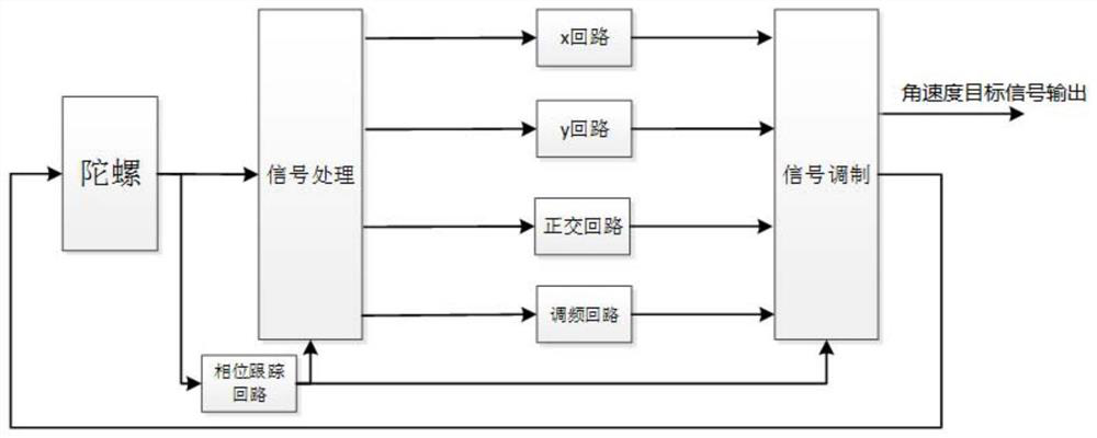
[0029] When there is no external angular velocity input, the angular velocity output of the gyro should be zero, but due to a series of factors such as processing errors and interference, the output of the gyro will not be zero, which is the zero position of the gyro. The traditional control scheme is to reflect the angular velocity output of the gyro through the change of a single force. The present invention reflects the angular velocity output of the gyro through the control force difference of the x and y t...


PUM


Abstract

The invention discloses a control circuit system based on the zero position self-calibration of a vibrating gyroscope. The system includes: a solid wave gyroscope; a signal demodulation module; an FPGA processing module, which includes five parallel loops, and the five loops are x loop, y loop, quadrature loop, phase tracking loop, frequency modulation loop; signal modulation module; the solid wave gyroscope, signal demodulation module, FPGA processing module, and signal modulation module are connected in sequence to form a signal closed loop. The invention demodulates the modal output of the resonant solid wave gyroscope, sends the demodulated signal to each loop for target control, and reflects the system by making a difference between the control forces of the X loop and the Y loop in the self-calibration mode In the absence of external angular velocity input, the output of the solid wave gyroscope is zero at this time through the subtraction of the X loop and the Y loop, and the zero position self-calibration is realized; the zero position error of the system can be greatly reduced by using the present invention , to increase the scaling factor of the system.

Description

technical field [0001] The invention relates to the field of inertial sensors, in particular to a control circuit system based on the zero position self-calibration of a vibrating gyroscope. Background technique [0002] Most of the existing solid wave gyroscopes work in the traditional force balance mode, which counteracts the influence of Gothic force on the precession state of the harmonic oscillator through the force balance loop. The magnitude of the control action represents the size of the Gothic force, and according to the proportional relationship between the Gothic force and the rotational speed, the rotational speed of the gyroscope and its carrier can be obtained through calculation. However, due to insufficient processing technology, uneven damping distribution, and frequency cracking, a series of problems will affect the accuracy of the gyroscope, resulting in the accuracy of the gyroscope in this mode has reached the technical bottleneck. Contents of the inv...

Claims


Application Information

Patent Timeline
Patent Type & Authority Patents(China)
IPC IPC(8): G01C25/00
CPCG01C25/005
Inventor 于翔宇赵万良成宇翔王伟荣义杰
Owner SHANGHAI AEROSPACE CONTROL TECH INST
Why Eureka
Try Eureka