A zeroing tool for wind turbine blades

A technology of wind power blades and tools, which is applied in wind power generation, control of wind turbines, wind turbines, etc., can solve the problems of non-standard blade zeroing process, unfavorable safe and stable operation of the unit, and influence on zeroing work, so as to improve operation Effects of reliability and power generation, simple structure, and easy operation

Active Publication Date: 2022-08-05
SHENHUA NEW ENERGY CO LTD +1
View PDF8 Cites 1 Cited by
  • Summary
  • Abstract
  • Description
  • Claims
  • Application Information

AI Technical Summary

Problems solved by technology

If the zero position deviation of a single blade is large, it will cause the vibration of the unit, which will cause a chain reaction, which is not good for the safe and stable operation of the unit. Therefore, this work requires high precision.
[0003] In the existing technology center, when the fan generator set is used for zero calibration of the blade, it is generally compared with a string or a cable tie. However, at present, the zero mark line of the blade of most wind power generator sets in the industry is not at the same level as the zero mark line of the hub casting. On the plane, such a comparison with the zero reticle line will often cause deviations with the naked eye, resulting in deviations in the zero position of the blades, and the cable ties are soft and easy to move. The whole process of zeroing the blades is very irregular, with large errors, and the temperature in winter is low. , the cable tie is fragile and easy to break, which affects the orderly progress of the zeroing work

Method used


Image

  • A zeroing tool for wind turbine blades
  • A zeroing tool for wind turbine blades
  • A zeroing tool for wind turbine blades

Examples


Embodiment Construction

[0035] The following will be combined with the attachment and specific embodiments to further explain the present invention in detail, but it does not limit the protection scope of the present invention.

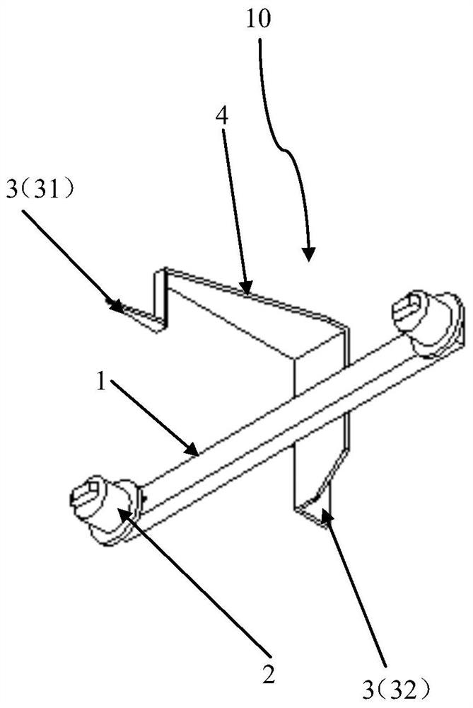
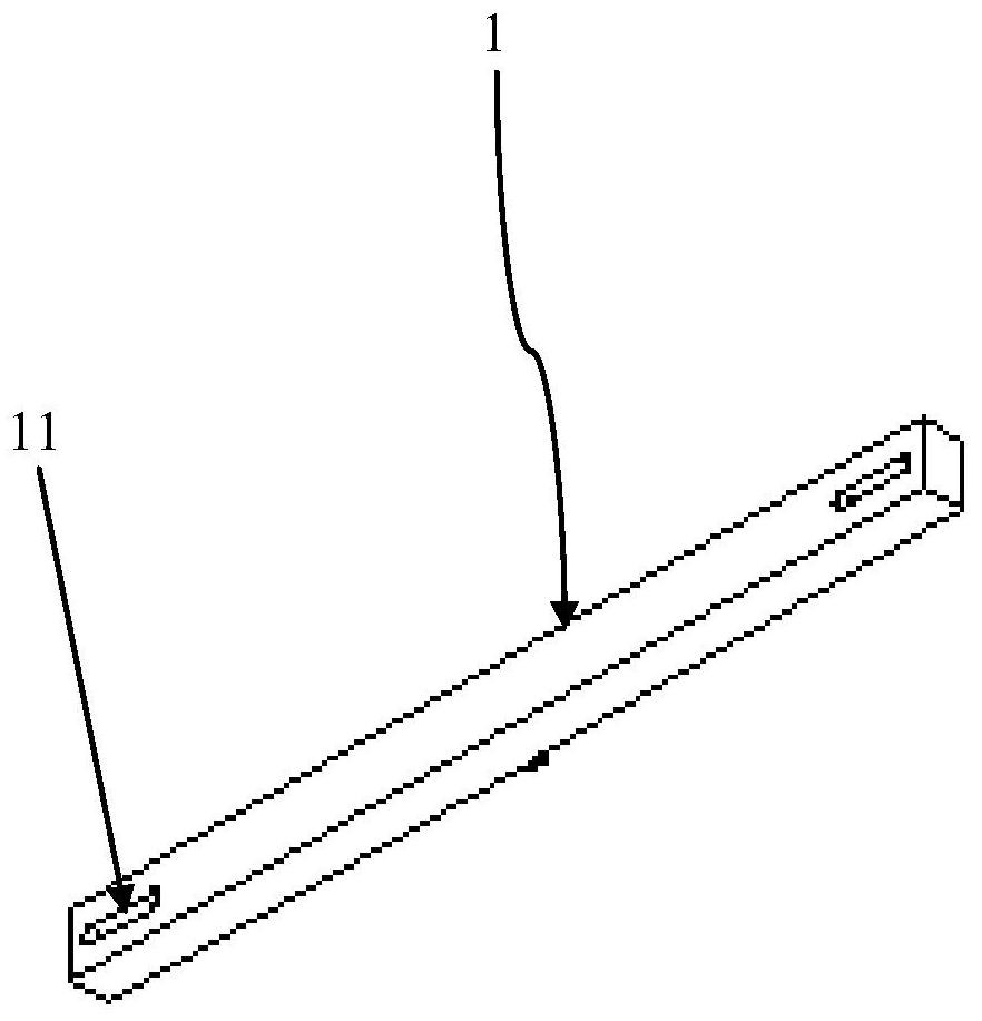
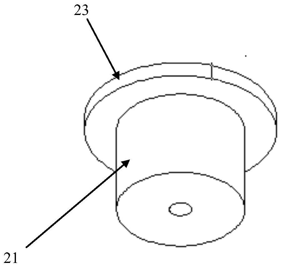
[0036] figure 1 The signaling shows the overall structure of the zero tool 10 of the invention embodiment. figure 2 The sign of the stem shows the overall structure of the support rod 1 of the invention. image 3 The signaling shows the cylindrical structure 21 in the limit device 2 of the present invention. Figure 4 The signaling shows the overall structure of fixed sales 221 in the restriction device 21 of the invention. Figure 5 The sign of the stem shows the supporting structure between the zero tool 10 of the zero tool 10 and the zero pointer 3 of the invention.

[0037] like figure 1 The present invention is used for zero tools 10 for wind power blades, including support rods, limited device 2, and zero pointer 3. Among them, the limit device 2 symmetrical is arranged at b...


PUM


Abstract

The invention provides a zeroing tool for wind power blades, comprising a support rod, a limiting device and a zeroing pointer. Wherein, the limiting devices are symmetrically arranged at both ends of the support rod, and the inner sides of the limiting devices can respectively form a fit with the outer sides of the two adjacent bolts on the hub for fixing the wind turbine blades. The zero-pointing pointer includes a first zero-pointing pointer for comparing the zero-marked line of the hub and a second zero-pointing pointer for comparing the zero-marking line of the wind turbine blade. The first pair of zero pointers and the limiting device are located on the same side of the support rod, and the second pair of zero pointers are arranged on the other side of the support rod. The projection on the horizontal plane of the part of the first pair of zero pointers that coincide with the zero scale line of the hub and the part of the second pair of zero pointers that coincide with the zero scale line of the wind turbine blade are on the same straight line. The zero setting tool of the invention has simple structure and easy operation, and can greatly improve the precision and efficiency of wind power blade zero setting, thereby effectively improving the power generation of the wind turbine and the operation reliability of the wind power set.

Description

Technical field [0001] The invention involves the field of maintenance technology in wind power generation units, which specifically involves a zero tool for wind power blades. Background technique [0002] The wind power generation units need to be calibrated by zero -to -zero blades every year. The accuracy of zero of the blades directly affects the use coefficient of wind energy and the availability of the crew. If the zero -bit deviation of a single blade will cause the crew to vibrate, which will cause a chain reaction and be unfavorable to the safe and stable operation of the unit. Therefore, the requirements for this work requirement are high. [0003] When the existing technology center, when the blasting crew performs zero -calibration work, it is generally compared with a thin rope or tie, but the zero -engraving lines of the blades of most wind turbines in the industry at present On the plane, comparing the zero -engraving line in this way, the naked eye observation of...

Claims


Application Information

Patent Timeline
Patent Type & Authority Patents(China)
IPC IPC(8): F03D80/50F03D13/30F03D7/04
CPCF03D80/50F03D13/30F03D7/0224Y02E10/72
Inventor 孙琪徐明王东常健包连祥王相菊李金辉李林懋石双磊
Owner SHENHUA NEW ENERGY CO LTD
Why Eureka
Try Eureka