Zero setting tool for wind power blade

A wind power blade and tool technology, applied in wind power generation, control of wind turbines, wind turbines, etc., can solve the problems of irregularity in the whole process of blade zeroing, affecting the zeroing work, vibration of the unit, etc., so as to improve operational reliability and Effects of power generation, improved accuracy and efficiency, and improved operational reliability

Active Publication Date: 2020-12-25
SHENHUA NEW ENERGY CO LTD +1
View PDF18 Cites 0 Cited by
  • Summary
  • Abstract
  • Description
  • Claims
  • Application Information

AI Technical Summary

Problems solved by technology

If the zero position deviation of a single blade is large, it will cause the vibration of the unit, which will cause a chain reaction, which is not good for the safe and stable operation of the unit. Therefore, this work requires high precision.
[0003] In the existing technology center, when the fan generator set is used for zero calibration of the blade, it is generally compared with a string or a cable tie. However, at present, the zero mark line of the blade of most wind power generator sets in the industry is not at the same level as the zero mark line of the hub casting. On the plane, such a comparison with the zero reticle line will often cause deviations with the naked eye, resulting in deviations in the zero position of the blades, and the cable ties are soft and easy to move. The whole process of zeroing the blades is very irregular, with large errors, and the temperature in winter is low. , the cable tie is fragile and easy to break, which affects the orderly progress of the zeroing work

Method used


Image

  • Zero setting tool for wind power blade
  • Zero setting tool for wind power blade
  • Zero setting tool for wind power blade

Examples


Embodiment Construction

[0035] The present invention will be further described in detail below in conjunction with the accompanying drawings and specific embodiments, but the protection scope of the present invention is not limited thereby.

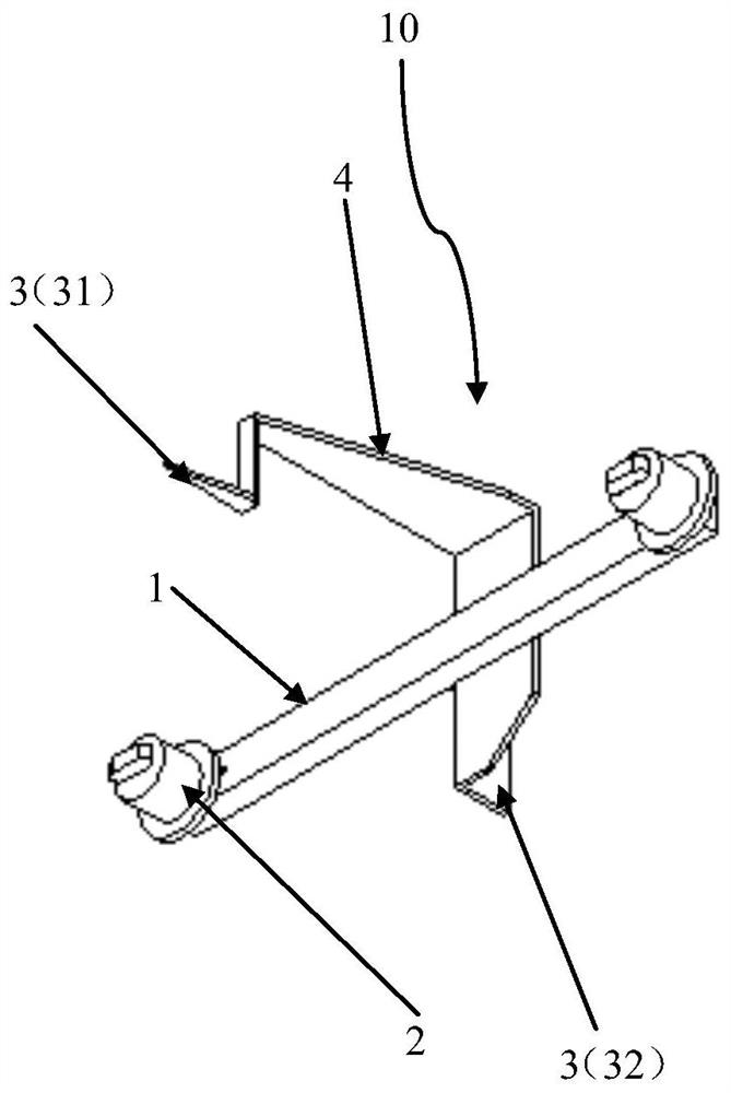
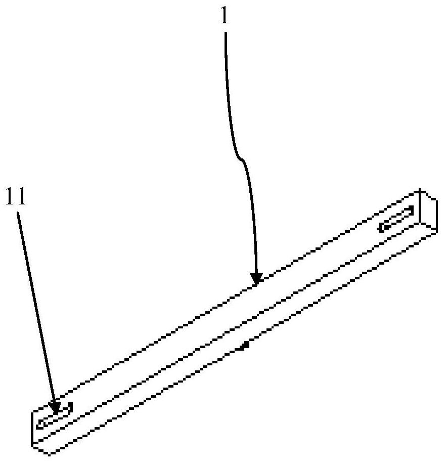
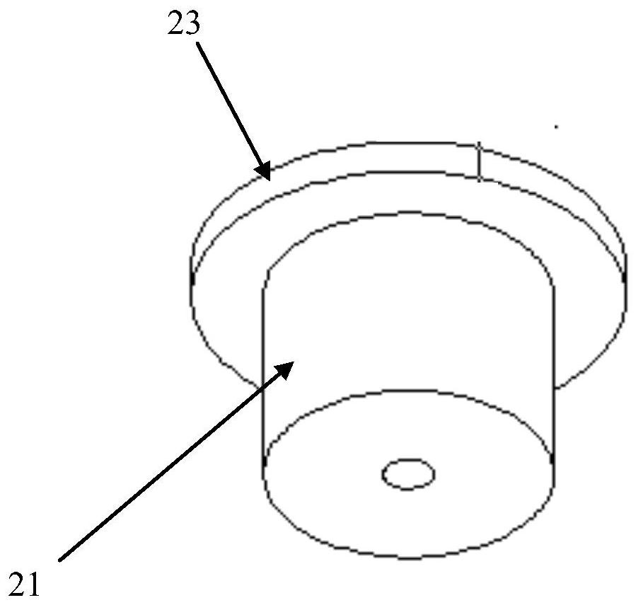
[0036] figure 1 The overall structure of the zero alignment tool 10 according to the embodiment of the present invention is schematically shown. figure 2 The overall structure of the support rod 1 according to the embodiment of the present invention is schematically shown. image 3 Schematically shows the cylindrical structure 21 in the limiting device 2 of the embodiment of the present invention. Figure 4 The overall structure of the fixing pin 221 in the limiting device 21 of the embodiment of the present invention is schematically shown. Figure 5 It schematically shows the cooperation structure between the bracket 4 of the zero alignment tool 10 and the zero alignment pointer 3 in the embodiment of the present invention.

[0037] Such as figure 1 As sh...


PUM


Abstract

The invention provides a zero setting tool for a wind power blade. The zero setting tool comprises a supporting rod, limiting devices and zero setting pointers. The limiting devices are symmetricallyarranged at the two ends of the supporting rod, and the inner side faces of the limiting devices can be matched with the outer side faces of two adjacent bolts, for fixing the wind power blade, on a hub respectively. The zero setting pointers comprise the first zero setting pointer for comparing hub zero marking lines and the second zero setting pointer for comparing wind power blade zero markinglines. The first zero setting pointer and the limiting devices are located on the same side of the supporting rod, and the second zero setting pointer is arranged on the other side of the supporting rod. The projection of the part, coinciding with the hub zero marking lines, of the first zero setting pointer and the projection of the part, coinciding with the wind power blade zero marking lines, of the second zero setting pointer on a horizontal plane are located on the same straight line. The zero setting tool is simple in structure and easy to operate, the zero setting precision and efficiency of the wind power blade can be improved to a great degree, and therefore the generating capacity of a draught fan and the running reliability of a wind turbine generator are effectively improved.

Description

technical field [0001] The invention relates to the technical field of wind power generator maintenance, in particular to a zero alignment tool for wind power blades. Background technique [0002] Wind turbines need to perform blade zero calibration every year. The accuracy of blade zero directly affects the utilization coefficient of wind energy and the availability of the unit. If the zero position deviation of a single blade is large, it will cause the vibration of the unit, which will cause a chain reaction, which is not good for the safe and stable operation of the unit. Therefore, this work requires high precision. [0003] In the existing technology center, when the fan generator set is used for zero calibration of the blade, it is generally compared with a string or a cable tie. However, at present, the zero mark line of the blade of most wind power generator sets in the industry is not at the same level as the zero mark line of the hub casting. On the plane, such a...

Claims


Application Information

Patent Timeline
Patent Type & Authority Applications(China)
IPC IPC(8): F03D80/50F03D13/30F03D7/04
CPCF03D80/50F03D13/30F03D7/0224Y02E10/72
Inventor 孙琪徐明王东常健包连祥王相菊李金辉李林懋石双磊
Owner SHENHUA NEW ENERGY CO LTD
Why Eureka
Try Eureka