Magnetic adsorption type positioning and rotating mechanism and using method thereof
A rotary mechanism, magnetic adsorption technology, applied in the direction of using mechanical devices, mechanical measuring devices, measuring devices, etc., can solve the problems of many axial and radial testing items, high technical level requirements, and inability to adapt to batch testing, etc. Avoid the effects of low rotation accuracy, secondary deformation, and large load
- Summary
- Abstract
- Description
- Claims
- Application Information
AI Technical Summary
Problems solved by technology
Method used
Image
Examples
Embodiment 1
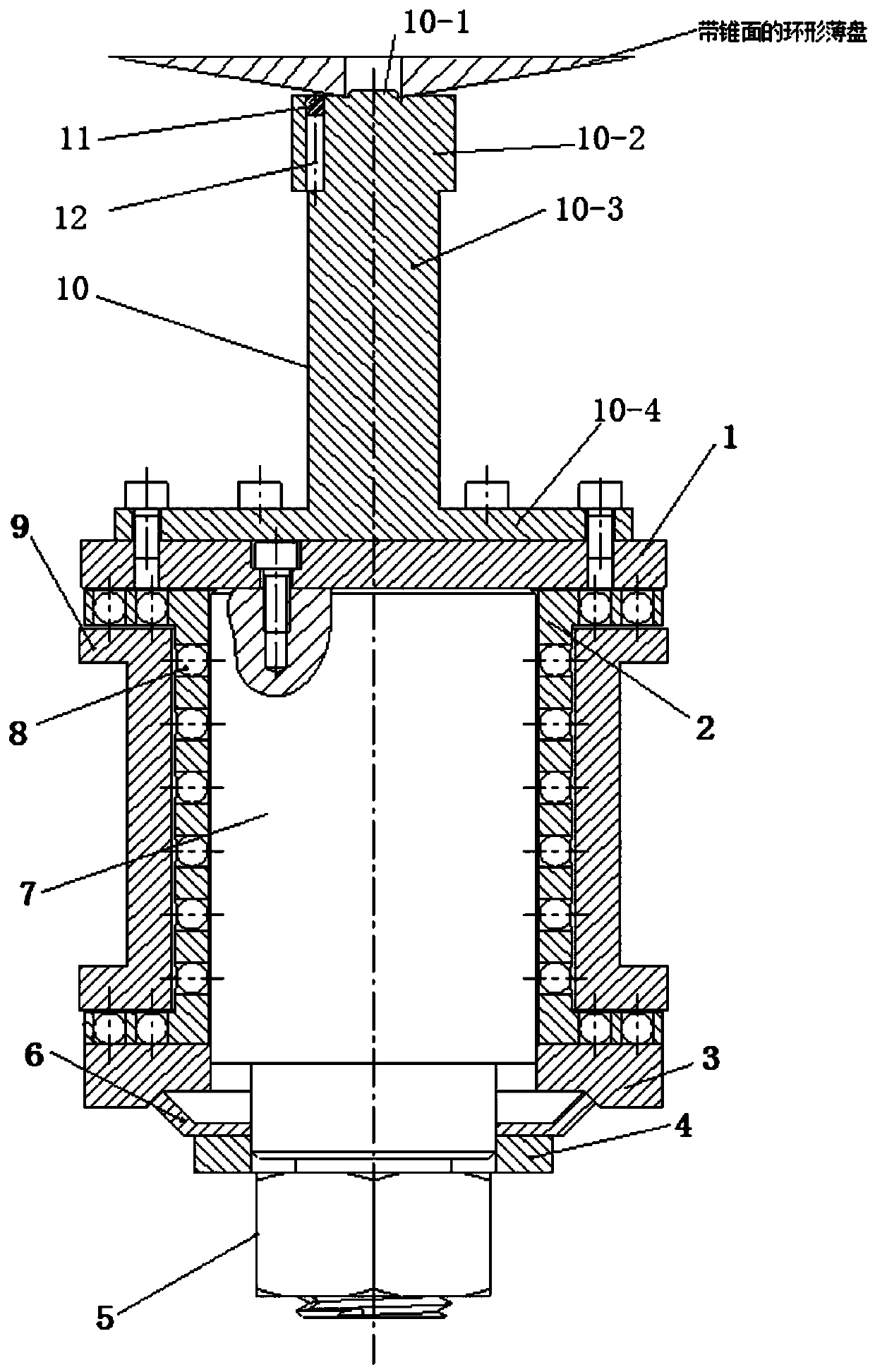
[0035] A magnetic adsorption positioning and rotating mechanism, including a positioning mechanism and a rotating mechanism, the positioning mechanism and the rotating mechanism form a whole that can rotate synchronously, and rotate under the drive of the driving motor, thereby realizing the rotation detection of the annular thin disk with a tapered surface .
[0036] The positioning mechanism includes a positioning platform 10, and the top of the positioning platform 10 is provided with a powerful magnetic column 11 for absorbing the annular thin disk with a tapered surface;
[0037] The slewing mechanism is a precision slewing shaft system with a slewing accuracy of the order of 0.001 mm, including an upper thrust cover 1, a main shaft 7, a shaft sleeve 9, a lower thrust cover 3 and a nut 5; the upper thrust cover 1 is a rotating part, which can realize the axial positioning of the entire shaft system, and is used as a connecting part connecting the positioning mechanism and...
Embodiment 2
[0040] A magnetic adsorption type positioning and turning mechanism, including a positioning mechanism and a turning mechanism, the positioning mechanism and the turning mechanism are fixedly connected to form a whole that can rotate synchronously, and it turns under the drive of the driving motor, so as to realize the alignment of the annular thin disk with a tapered surface. rotation detection.
[0041] The positioning mechanism includes a positioning platform 10. The positioning platform 10 is vertically arranged and has a stepped shaft structure. From top to bottom, there are first shaft section 10-1, second shaft section 10-2, and third shaft section. Section 10-3 and the fourth shaft section 10-4, the axial height of the first shaft section 10-1 is 5mm, the shaft diameter is configured according to the central hole of the annular thin disk with a tapered surface, and the two have a clearance fit, The gap is 0.01 mm; the shaft diameter of the second shaft section 10-2 is ...
Embodiment 3
[0045] A magnetic adsorption type positioning and turning mechanism, including a positioning mechanism and a turning mechanism, the positioning mechanism and the turning mechanism are fixedly connected to form a whole that can rotate synchronously, and it turns under the drive of the driving motor, so as to realize the alignment of the annular thin disk with a tapered surface. rotation detection.
[0046] The positioning mechanism includes a positioning platform 10. The positioning platform 10 is vertically arranged and has a stepped shaft structure. From top to bottom, there are first shaft section 10-1, second shaft section 10-2, and third shaft section. Section 10-3 and the fourth shaft section 10-4, the axial height of the first shaft section 10-1 is 5mm, the shaft diameter is configured according to the central hole of the annular thin disk with a tapered surface, and the two have a clearance fit, The gap is 0.01 mm; the shaft diameter of the second shaft section 10-2 is ...
PUM
 Abstract
Description
Claims
Application Information
 - R&D
- Intellectual Property
- Life Sciences
- Materials
- Tech Scout
- Unparalleled Data Quality
- Higher Quality Content
- 60% Fewer Hallucinations
Browse by: Latest US Patents, China's latest patents, Technical Efficacy Thesaurus, Application Domain, Technology Topic, Popular Technical Reports.
© 2025 PatSnap. All rights reserved.Legal|Privacy policy|Modern Slavery Act Transparency Statement|Sitemap|About US| Contact US: help@patsnap.com


