
Batch cutting device for bricks for building construction

A construction and cutting device technology, which is applied in the direction of working accessories, manufacturing tools, stone processing tools, etc., can solve the problem that it is difficult to ensure the inclination or size of the section of half a brick is consistent, the cutting disc and motor are damaged, and the vibration force of the cutting device is large And other issues

Active Publication Date: 2021-05-04
明光市白云建筑安装工程有限责任公司
View PDF22 Cites 0 Cited by
  • Summary
  • Abstract
  • Description
  • Claims
  • Application Information

AI Technical Summary

Problems solved by technology

Bricks are an indispensable raw material in buildings, especially when using standard bricks. The size of a standard brick is a solid brick of 240mm×115mm×53mm. During the construction of a building, the finished bricks are all of the same size. As a result, when building some corners, half bricks or small bricks of different shapes or sizes are required as fillings, and sometimes the section of the half brick has a certain angle of slope, and many bricks are required in the process of building corners. For this kind of half brick, the brick cutting machine currently on the market can cut a small amount of bricks at a time, which affects the construction progress, and it is difficult to ensure that the inclination or size of the half brick section after each cutting is consistent, and when cutting bricks During the cutting process, the reaction force of the cutting disc and the motor is relatively large, which will not only cause a large vibration force of the cutting device, but also damage the cutting disc and the motor. Therefore, in order to solve the above defects, a new type of construction brick is urgently needed Block Batch Cutting Device

Method used


Image

  • Batch cutting device for bricks for building construction
  • Batch cutting device for bricks for building construction
  • Batch cutting device for bricks for building construction

Examples


Embodiment Construction

[0017] Below in conjunction with accompanying drawing and specific embodiment the present invention is described in further detail:

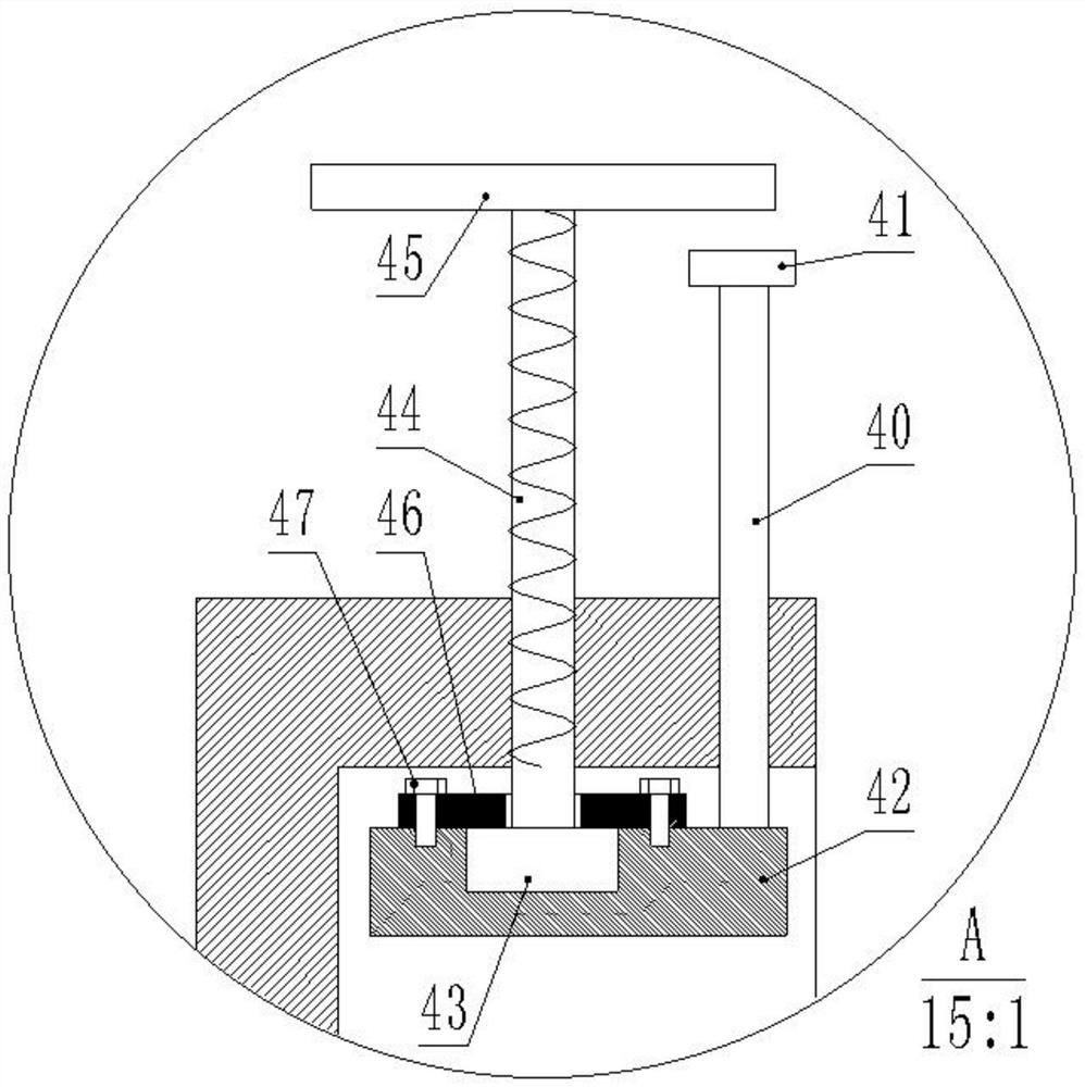
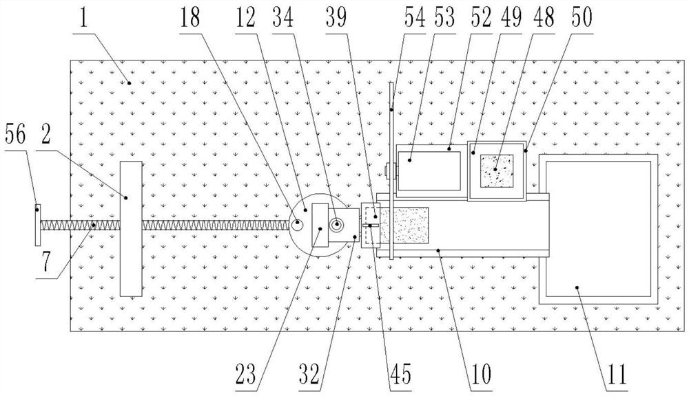
[0018] Such as figure 1 , figure 2 , image 3 , Figure 4 , Figure 5 , Image 6As shown, a batch cutting device for bricks for building construction includes a base 1, a support plate 2 is fixed on one side of the top surface of the base 1, and a T-shaped chute 3 is provided at the center of the top surface of the base 1. The first T-shaped slider 4 and the second T-shaped slider 5 are slidably provided in the T-shaped chute 3, and the top end of the T-shaped slider 4 protrudes from the T-shaped chute 3 and is fixed with a first sleeve 6. A threaded rod 7 is sleeved inside the first sleeve 6, and the threaded rod 7 is rotatably connected with the first sleeve 6. Two limit rings 8 are fixedly sleeved on the threaded rod 7, and the two limit rings 8 are symmetrically attached to each other. It is arranged on both sides of the first sleeve ...


PUM


Abstract

The invention discloses a brick batch cutting device for building construction, which comprises a base, a support plate is fixed on one side of the top surface of the base, and a T-shaped sliding groove is opened at the center of the top surface of the base. This device can cut multiple bricks in the slot at one time, so as to achieve the purpose of cutting multiple bricks at one time, so that this device can be applied to the large-scale cutting of bricks, which can not only effectively improve work efficiency, but also It can also effectively ensure that the inclination or size of the half brick section after each cut is consistent, and the length of the brick to be cut can be precisely controlled by turning the threaded rod with the handle, and the brick can be adjusted according to the construction requirements by turning the mounting plate through the rotating shaft The angle between the block and the cutting disc can precisely control the inclination of the end face of the brick after being cut, and through the setting of two rubber rings, it can effectively buffer the reaction force and the motor generated when the cutting disc cuts the brick. Vibration force generated during operation.

Description

technical field [0001] The invention relates to the field of building construction, in particular to a brick batch cutting device for building construction. Background technique [0002] Due to the vigorous development of the real estate industry, the construction industry has increasingly become a pillar industry in economic development, which has also led to the rapid development of the construction machinery industry. Bricks are an indispensable raw material in buildings, especially when using standard bricks. The size of a standard brick is a solid brick of 240mm×115mm×53mm. During the construction of a building, the finished bricks are all of the same size. As a result, when building some corners, half bricks or small bricks of different shapes or sizes are required as fillings, and sometimes the section of the half brick has a certain angle of slope, and many bricks are required in the process of building corners. For this kind of half brick, the brick cutting machine...

Claims


Application Information

Patent Timeline
Patent Type & Authority Patents(China)
IPC IPC(8): B28D1/24B28D7/00B28D7/04
CPCB28D1/24B28D7/00B28D7/043
Inventor 周强
Owner 明光市白云建筑安装工程有限责任公司
Learn More