
A U-shaped workpiece automatic welding tracking system and working method based on Leisai controller

A tracking system and working method technology, applied in welding equipment, manufacturing tools, welding equipment, etc., can solve the problems of inaccurate welding point search, high algorithm complexity, reduced measurement accuracy, etc., to ensure timeliness and high real-time performance. , The effect of improving welding accuracy and efficiency

Active Publication Date: 2021-09-28
SUZHOU CHIEN SHIUNG INST OF TECH
View PDF7 Cites 0 Cited by
  • Summary
  • Abstract
  • Description
  • Claims
  • Application Information

AI Technical Summary

Problems solved by technology

Sun Junhua proposed to use the nearest point iterative algorithm, which has high real-time performance, but the measurement accuracy will be reduced when noise interferes; Yang Qiang proposed to use genetic algorithm, but the algorithm complexity is high, and a host computer is needed, so the real-time performance is not high; Zheng L, Tan Zhouwen proposed A contour matching algorithm based on least squares is adopted, which has high real-time performance. However, due to the influence of light sources, isolated cluster points will appear when collecting signals on the side of the workpiece, and the error of using this algorithm is relatively large.
[0003] At the same time, during the working process of the existing welding tracking system, the search of welding points on the weld seam often has inaccurate phenomena, especially for some irregular workpieces. It is found through experiments that when scanning a U-shaped workpiece, the inflection point data error probability is 90% when the plane enters the side, or the inflection point data changes when the side enters the plane. , so the existing welding tracking system still needs to be improved

Method used


Image

  • A U-shaped workpiece automatic welding tracking system and working method based on Leisai controller
  • A U-shaped workpiece automatic welding tracking system and working method based on Leisai controller
  • A U-shaped workpiece automatic welding tracking system and working method based on Leisai controller

Examples


Embodiment 1

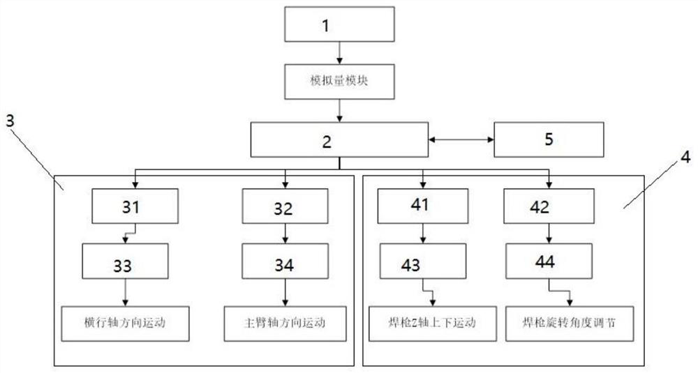
[0059] A U-shaped workpiece automatic welding tracking system based on the Leisai controller, including: a four-axis welding tracking system, a mechanical arm and a welding torch, the four-axis welding tracking system is set on the mechanical arm, and the welding torch is set on the mechanical arm , wherein the four-axis welding tracking system is provided with a laser position sensor 1, a controller 2, a set of mechanical arm control mechanisms 3 for controlling the operation of the mechanical arm, a set of control mechanisms for controlling the up and down movement of the welding torch and the adjustment of the rotation angle The welding torch control mechanism 4 and the display screen 5, the output end of the laser position sensor 1 is connected with the input end of the controller 2, and the output end of the controller 2 is simultaneously connected with the input end of the mechanical arm control mechanism 3 and the welding torch control mechanism 4, and the display screen...

Embodiment 2

[0064] A U-shaped workpiece automatic welding tracking system based on the Leisai controller, including: a four-axis welding tracking system, a mechanical arm and a welding torch, the four-axis welding tracking system is set on the mechanical arm, and the welding torch is set on the mechanical arm , wherein the four-axis welding tracking system is provided with a laser position sensor 1, a controller 2, a set of mechanical arm control mechanisms 3 for controlling the operation of the mechanical arm, a set of control mechanisms for controlling the up and down movement of the welding torch and the adjustment of the rotation angle The welding torch control mechanism 4 and the display screen 5, the output end of the laser position sensor 1 is connected with the input end of the controller 2, and the output end of the controller 2 is simultaneously connected with the input end of the mechanical arm control mechanism 3 and the welding torch control mechanism 4, and the display screen...

Embodiment 3

[0074] A U-shaped workpiece automatic welding tracking system based on the Leisai controller, including: a four-axis welding tracking system, a mechanical arm and a welding torch, the four-axis welding tracking system is set on the mechanical arm, and the welding torch is set on the mechanical arm , wherein the four-axis welding tracking system is provided with a laser position sensor 1, a controller 2, a set of mechanical arm control mechanisms 3 for controlling the operation of the mechanical arm, a set of control mechanisms for controlling the up and down movement of the welding torch and the adjustment of the rotation angle The welding torch control mechanism 4 and the display screen 5, the output end of the laser position sensor 1 is connected with the input end of the controller 2, and the output end of the controller 2 is simultaneously connected with the input end of the mechanical arm control mechanism 3 and the welding torch control mechanism 4, and the display screen...


PUM


Abstract

The invention discloses a U-shaped workpiece automatic welding tracking system based on a Leisai controller. First, the data point data on the U-shaped workpiece is scanned by a laser position sensor; then the laser position sensor sends the scanned information to the The controller, the controller corrects the data point data through the optimization algorithm to form a weld profile curve with a high degree of matching with the U workpiece, that is, to optimize the weld profile curve obtained by the laser position sensor; then the controller controls according to the corrected data point data The mechanical arm control mechanism and the welding torch control mechanism work; after the controller has adjusted the positions of the mechanical arm and the welding torch in the previous step, the U-shaped workpiece can be welded; the present invention optimizes the path of the data points through an algorithm, and Compared with the existing technology, the cost is saved, and there is no need to designate a host computer for algorithm optimization, which ensures the timeliness of data optimization.

Description

technical field [0001] The invention belongs to the technical field of automatic control systems, in particular to an automatic welding tracking system for U-shaped workpieces based on a Leisai controller and an optimization control method. Background technique [0002] Welding technology is widely used in various fields such as industrial production, energy, transportation, and electrical engineering, and plays an important role in the development of the national economy. Intelligence and automation replace the original manual welding, ensuring welding quality and welding efficiency. The welding automation in foreign countries has reached more than 80%, and the welding automation in my country's manufacturing industry has basically reached 30%. With the introduction and development of intelligent manufacturing, higher requirements have been put forward for welding automation, and a welding tracking system based on sensor technology has been produced. The general welding tr...

Claims


Application Information

Patent Timeline
Patent Type & Authority Patents(China)
IPC IPC(8): B23K37/00B23K9/127
CPCB23K9/127B23K9/1274B23K37/00
Inventor 张晓芳张子喻程长远秦婧胡宏梅
Owner SUZHOU CHIEN SHIUNG INST OF TECH
Learn More