
A kind of transmission mechanism of placement machine with pcb board fixing device

A PCB board and fixing device technology, which is applied in the orientation of circuit board tools, assembling printed circuits with electrical components, and electrical components, etc., can solve the problems of increasing labor costs, not setting PCB fixing devices, and not being able to transport PCB boards of different sizes. , to achieve the effect of reducing labor input, less labor input, and improving patch efficiency

Active Publication Date: 2020-12-04
四川恒立泰科技有限公司
View PDF1 Cites 1 Cited by
  • Summary
  • Abstract
  • Description
  • Claims
  • Application Information

AI Technical Summary

Problems solved by technology

[0006] Although the above-mentioned invention application has the characteristics of saving labor costs, the invention does not have a PCB fixing device. When the placement machine mounts the PCB board, the PCB board will move on the operation board, resulting in the inability to effectively carry out the PCB board. Chips are prone to produce more defective products and increase costs
[0007] Although in the prior art, the PCB board is transported to the placement machine through the conveyor belt for placement, but because the size of the existing conveyor belt cannot be changed, PCB boards of different sizes cannot be transported, so PCB boards of different sizes are equipped with corresponding Adapted conveyor belts lead to extremely high investment costs and increase the floor area. In order to reduce costs and reduce the floor space of the machine, some PCB boards are manually placed on the operation table of the placement machine for placement. Resulting in extremely low efficiency and increased labor costs

Method used


Image

  • A kind of transmission mechanism of placement machine with pcb board fixing device
  • A kind of transmission mechanism of placement machine with pcb board fixing device
  • A kind of transmission mechanism of placement machine with pcb board fixing device

Examples


Embodiment Construction

[0030] The technical solution of the present invention will be further described in detail below in conjunction with the accompanying drawings, but the protection scope of the present invention is not limited to the following description.

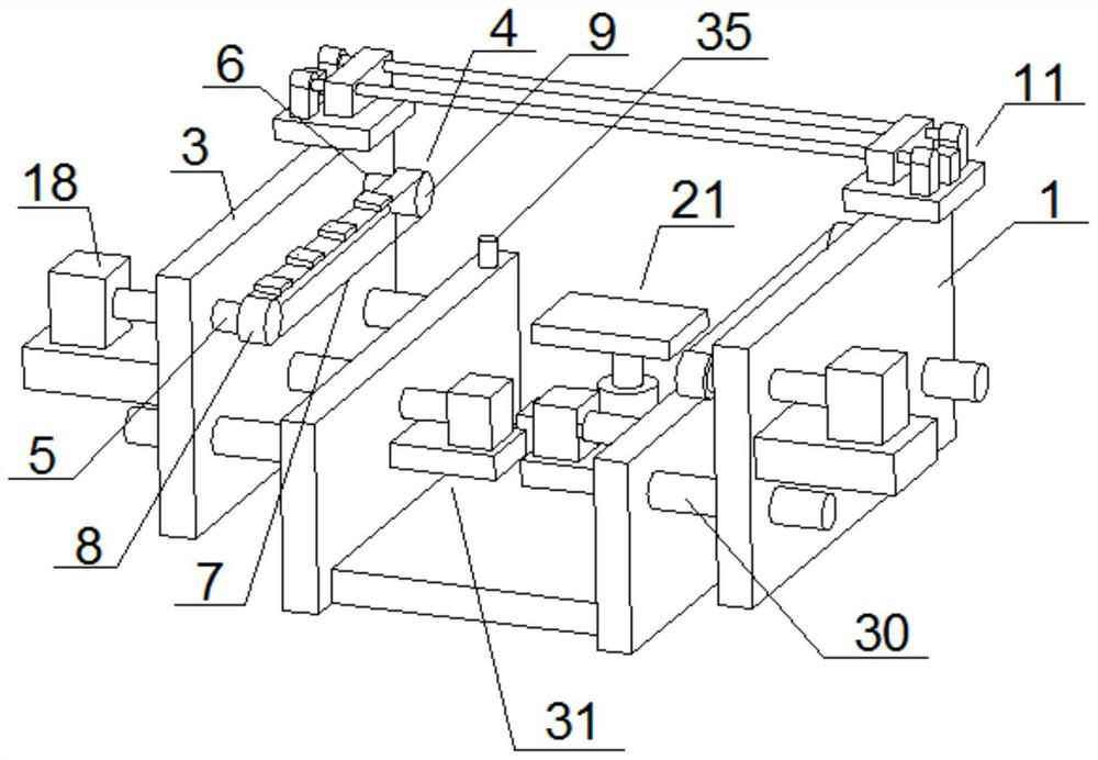
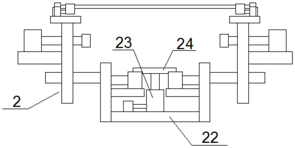
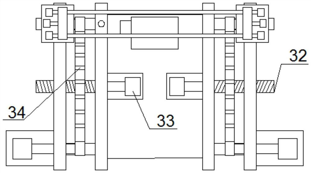
[0031] Such as Figure 1 to Figure 6As shown, a placement machine transmission mechanism with a PCB board fixing device includes a transmission frame 1 and two PCB board conveying devices 2, and the two PCB board conveying devices 2 are symmetrically arranged on both sides of the transmission frame 1, and the PCB The plate conveying device 2 includes a mounting plate 3 and a belt conveying device 4 arranged on the mounting plate 3, and the mounting plate 3 is movably arranged on the transmission frame 1;

[0032] Through the active setting of the mounting board, the distance between the two PCB board conveying devices 2 can be changed, so as to realize the conveyance of PCB boards of different sizes, reduce the investment of machines, reduc...


PUM


Abstract

The invention discloses a chip mounter transmission mechanism with a PCB fixing device. The chip mounter transmission mechanism comprises a transmission mechanism and two PCB conveying devices. The two PCB conveying devices are symmetrically arranged on the two sides of the transmission rack. The PCB conveying device comprises a mounting plate and a belt conveying device arranged on the mounting plate. The mounting plate is movably arranged on the transmission rack, and the distance between the two PCB conveying devices is changed through the movable arrangement of the mounting plate, so thatPCBs with different sizes are conveyed, the investment of a machine is reduced, the cost is reduced, the working efficiency is improved, and meanwhile, the labor cost is reduced. The mechanism furthercomprises a PCB fixing device. The PCB conveyed by the PCB conveying device is fixed through the PCB fixing device. The PCB fixing device is simple in structure and convenient to use, a chip mountercan carry out chip mounting operation conveniently, the chip mounter can carry out chip mounting on PCBs better, and defective products are greatly reduced. Meanwhile, the PCBs of different sizes canbe fixed, and the application range of the PCB fixing device is widened.

Description

technical field [0001] The invention relates to the field of SMT placement machines, in particular to a placement machine transmission mechanism with a PCB board fixing device. Background technique [0002] Surface mount technology (English full name Surface Mount Technology, referred to as SMT), is currently the most popular technology and process in the electronic assembly industry. It is a kind of non-pin or short-lead surface mount components (English abbreviation SMC / SMD, Chinese called chip components) mounted on the surface of a printed circuit board (English full name Printed Circuit Board, referred to as PCB) or other substrates. On the surface, it is a circuit assembly technology that is soldered and assembled by methods such as reflow soldering or dip soldering. [0003] The placement machine is a device used to achieve high-speed and high-precision placement of chip components. It is configured after the dispenser or screen printing machine, and the surface moun...

Claims


Application Information

Patent Timeline
Patent Type & Authority Patents(China)
IPC IPC(8): H05K3/00H05K3/34
CPCH05K3/0008H05K3/341
Inventor 陈继红
Owner 四川恒立泰科技有限公司
Learn More