
Remote real-time monitoring method and device for nuclear radiation source equipment

A monitoring device and real-time monitoring technology, applied in radiation measurement, radiation intensity measurement, instruments, etc., can solve problems such as affecting the accuracy of radiation sources, surrounding radiation intensity, and monitoring equipment failure.

Pending Publication Date: 2020-04-10
SOUTH CHINA INST OF ENVIRONMENTAL SCI MEP +1
View PDF1 Cites 1 Cited by
  • Summary
  • Abstract
  • Description
  • Claims
  • Application Information

AI Technical Summary

Problems solved by technology

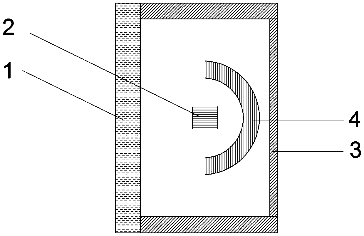
For mobile nuclear radiation source flaw detection equipment, its nuclear radiation source is usually installed in a safety shielding box (lead or depleted uranium material), and the radiation intensity around the instrument is not high, but when the equipment (such as a gamma flaw detector) performs flaw detection operations , the radiation source will be exported out of the shielding box, and the radiation source is always exported from one direction, which will cause the surrounding radiation intensity to be particularly large, which will easily cause irreversible damage to the monitoring equipment installed in the short distance; if the sensitivity of the nuclear radiation detection module If the sensitivity is too low, it will affect the accuracy of the radiation source detection results; if the sensitivity is too high, the monitoring equipment will be easily destroyed by high-intensity radiation and become invalid

Method used


Image

  • Remote real-time monitoring method and device for nuclear radiation source equipment
  • Remote real-time monitoring method and device for nuclear radiation source equipment
  • Remote real-time monitoring method and device for nuclear radiation source equipment

Examples


Embodiment Construction

[0052] The following will clearly and completely describe the technical solutions in the embodiments of the present invention with reference to the accompanying drawings in the embodiments of the present invention. Obviously, the described embodiments are only some, not all, embodiments of the present invention. Based on the embodiments of the present invention, all other embodiments obtained by persons of ordinary skill in the art without making creative efforts belong to the protection scope of the present invention.

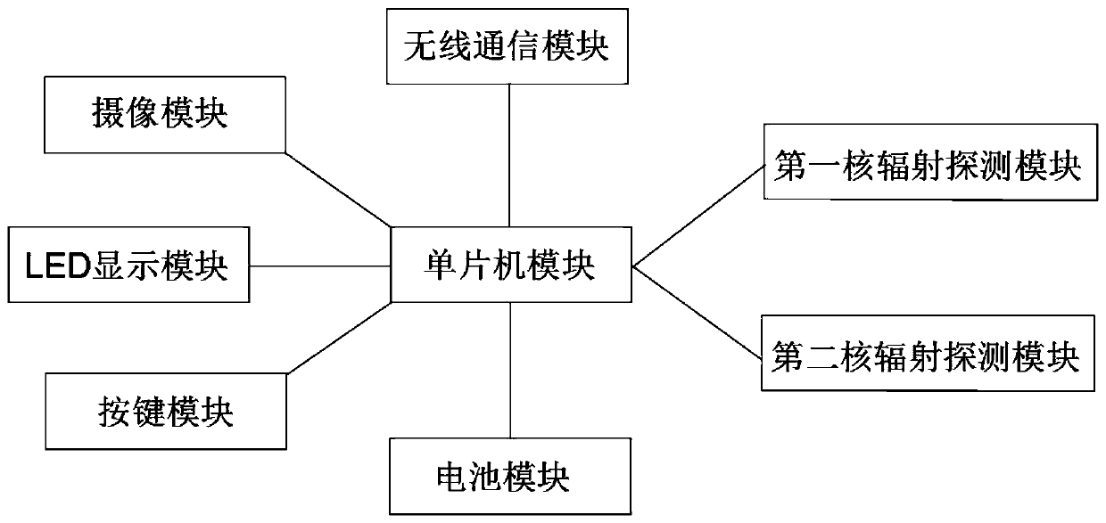
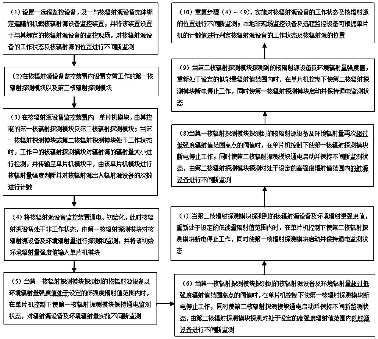
[0053] See attached Figure 1-5 , the remote real-time monitoring method for nuclear radiation source equipment provided by the present invention comprises the following steps:

[0054] (1) Set up a remote monitoring device, and an airborne nuclear radiation source equipment monitoring device bound to the casing of the nuclear radiation source equipment to follow, and set the device at the monitoring site of the nuclear radiation source equipment bound to it. ...


PUM


Abstract

The invention discloses a remote real-time monitoring method for nuclear radiation source equipment. The remote real-time monitoring method comprises the following steps: (1) setting a remote monitoring device and an airborne monitoring device; (2) arranging nuclear radiation detection modules which work alternately; (3) the single-chip microcomputer module controlling the nuclear radiation detection module and counting; (4) electrifying the device; (5) when the radiation quantity is in an emission value range, the first nuclear radiation detection module carrying out monitoring; (6) when theradiation quantity exceeds a low-intensity high-point threshold value, starting a second nuclear radiation detection module; (7) when the radiation quantity is in the low-energy range again, startingthe first nuclear radiation detection module; (8) if the radiant quantity exceeds the low-intensity high-point threshold value again, starting a second nuclear radiation detection module; (9) when theradiation quantity is in the low-energy range again, starting the first nuclear radiation detection module; (10) repeating the steps (4)-(9) to monitor the nuclear radiation source equipment; and thenuclear radiation source device can be judged according to the counting value of the single-chip microcomputer. The method can prevent the nuclear radiation source device from being damaged.

Description

technical field [0001] The invention relates to the field of radiation safety monitoring, in particular to a remote real-time monitoring method and device for nuclear radiation source equipment. Background technique [0002] With the rapid development of nuclear technology and information technology, the application market of nuclear radiation sources is becoming more and more extensive. Through applications in industry, agriculture, medicine, and research, radiation sources provide enormous benefits to humanity and society, and make important contributions to scientific and technological progress. At the same time, the poor management of radiation sources has caused serious harm to the environment and human health. At present, the traditional supervision methods of radiation sources are mainly locking, warning and human care, etc. However, loss and leakage accidents abound due to human factors, which pose a huge threat to society and public safety. [0003] In the existin...

Claims


Application Information

Patent Timeline
Patent Type & Authority Applications(China)
IPC IPC(8): G01T1/18G01T7/00H04N7/18
CPCG01T1/18G01T7/00H04N7/18
Inventor 陈思莉虢清伟陈富章甘汨姚旭忠罗雪婷徐岳
Owner SOUTH CHINA INST OF ENVIRONMENTAL SCI MEP
Learn More