Ignition-supplementing combustion chamber and gas turbine system

A gas turbine and combustor technology, which is applied in the direction of using various fuel combustion, combustion methods, combustion types, etc., can solve the problems of the maximum state drop of flue gas temperature, large gap between peak and valley electricity prices, and limited adjustment range, etc., to achieve structural and Ease of control, reduced emissions, and improved regulation range

Pending Publication Date: 2020-04-10
新奥能源动力科技(上海)有限公司
View PDF0 Cites 2 Cited by
  • Summary
  • Abstract
  • Description
  • Claims
  • Application Information

AI Technical Summary

Problems solved by technology

[0002] The cooling, heating and power distributed energy system based on micro-small gas turbines is booming. At present, there is a large gap between peak and valley electricity prices and different power demands. However, adjusting the power output by using gas turbines to operate in some working conditions or even shutting down in valleys will lead to a decrease in heat output. As a result, great changes have taken place. Therefore, it is generally required that the electric-heat ratio of distributed energy systems be adjustable. The current adjustment technical means mainly include waste heat boilers with supplementary combustion or bromine coolers, and technologies such as adjustable regenerator ratios. However, the above-mentioned The adjustment range is very limited. For example, if it is equipped with a waste heat boiler or a bromine cooler with supplementary combustion, the adjustment range of the thermoelectric ratio is only about 40%, and it will cause the maximum flue gas temperature to drop.

Method used


Image

  • Ignition-supplementing combustion chamber and gas turbine system
  • Ignition-supplementing combustion chamber and gas turbine system

Examples


Embodiment Construction

[0020] The following will clearly and completely describe the technical solutions in the embodiments of the present invention with reference to the accompanying drawings in the embodiments of the present invention. Obviously, the described embodiments are only some, not all, embodiments of the present invention. Based on the embodiments of the present invention, all other embodiments obtained by persons of ordinary skill in the art without making creative efforts belong to the protection scope of the present invention.

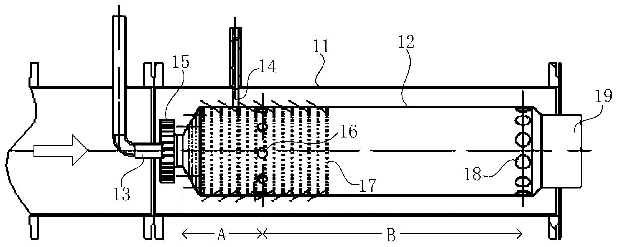
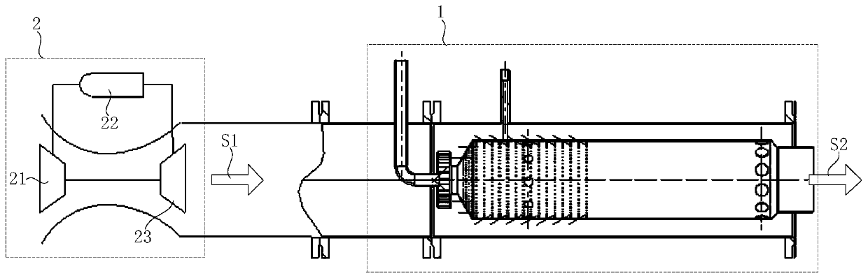
[0021] Such as figure 1 with figure 2 As shown, a post-combustion combustor 1 provided by the embodiment of the present invention includes a combustor casing 11, a flame tube 12, a fuel nozzle 13 and an igniter 14, and the combustor casing 11 is arranged behind the gas turbine 2. In the gas flue, the flame tube 12 is located in the combustion chamber casing 11, including the main combustion zone A and the middle zone B arranged in sequence from the front end...


PUM


Abstract

The invention relates to the technical field of gas turbines, and discloses an ignition-supplementing combustion chamber and a gas turbine system. The ignition-supplementing combustion chamber comprises a combustion chamber shell, a flame barrel, a fuel nozzle and an igniter, wherein the combustion chamber shell is arranged in an exhaust flue behind a gas turbine, the flame barrel is located in the combustion chamber shell and comprises a main combustion region and an intermediate region which are sequentially arranged from the front end to the rear end, the fuel nozzle is arranged at the front end of the flame barrel, and the igniter is arranged on the position, opposite to the main combustion region, of the side wall of the flame barrel. The ignition-supplementing combustion chamber is arranged in the exhaust flue of the gas turbine, so that the exhaust temperature of the gas turbine system can be remarkably improved under various working conditions, the thermoelectric ratio can be effectively improved, and the theoretical adjusting range can reach 100%; and therefore, the thermoelectric ratio adjusting range of a hot and cold electric distribution type energy system based on thegas turbine can be optimized.

Description

technical field [0001] The invention relates to the technical field of gas turbines, in particular to an afterburning combustion chamber and a gas turbine system. Background technique [0002] The cooling, heating and power distributed energy system based on micro-small gas turbines is booming. At present, there is a large gap between peak and valley electricity prices and different power demands. However, adjusting the power output by using gas turbines to operate in some working conditions or even shutting down in valleys will lead to a decrease in heat output. As a result, great changes have taken place. Therefore, it is generally required that the electric-heat ratio of distributed energy systems be adjustable. The current adjustment technical means mainly include waste heat boilers with supplementary combustion or bromine coolers, and technologies such as adjustable regenerator ratios. However, the above-mentioned The adjustment range is very limited. For example, if eq...

Claims


Application Information

Patent Timeline
Patent Type & Authority Applications(China)
IPC IPC(8): F23C5/08F23J15/08F23G7/06
CPCF23C5/08F23G7/06F23J15/08
Inventor 李成勤许裕栗安履东崔扬泽张明明顾明恒侯晨莉
Owner 新奥能源动力科技(上海)有限公司
Why Eureka
Try Eureka