Brake disc liquid cooling circulation method

A cold cycle and brake fluid technology, applied in the field of brake disc cooling, can solve problems such as waste of water resources, affecting driving safety, etc., and achieve excellent cooling effect

Inactive Publication Date: 2020-04-10
CHENGDU SHUANGLIU JINSHI MACHINERY
View PDF10 Cites 2 Cited by
  • Summary
  • Abstract
  • Description
  • Claims
  • Application Information

AI Technical Summary

Problems solved by technology

[0003] The purpose of the present invention is to provide a liquid cooling circulation method for the brake disc, which solves the problem that when the disc brake disc is cooled by the traditional air cooling method, it is necessary to cooperate with the water shower to cool the disc brake disc, but this method will cause water Waste of resources and issues affecting driving safety

Method used


Image

  • Brake disc liquid cooling circulation method
  • Brake disc liquid cooling circulation method
  • Brake disc liquid cooling circulation method

Examples


Embodiment

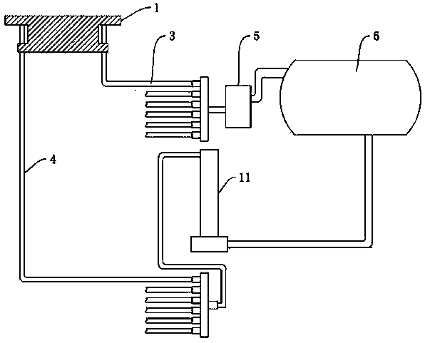
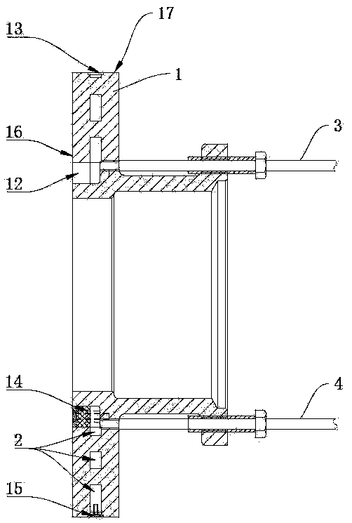
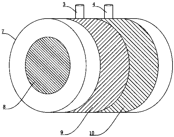
[0022] Figure 1-3 A preferred embodiment of the brake disc liquid cooling circulation method of the present invention is shown. The brake disc liquid cooling circulation method in this embodiment includes the following steps: S1, the air cooling port of the disc brake disc 1 with the cooling cavity 2 is cooled. Blocking to form a sealed cavity, and set the water inlet pipe 3 and the water outlet pipe 4 connected with the cooling chamber 2 on the disc brake disc 1; S2, use the water pump 5 to extract the circulating water in the water tank 6 of the vehicle, and make the circulating water flow from the inlet The water pipe 3 flows into the cooling chamber 2 ; S3 , the circulating water in the cooling chamber 2 after cooling the disc brake disc 1 flows out from the water outlet pipe 4 and returns to the water tank 6 .

[0023] Block the air cooling port of the original cooling cavity 2 in the disc brake disc 1, and then make the cooling cavity 2 in a closed state, set the water ...


PUM


Abstract

The invention relates to a brake disc cooling method, in particular to a brake disc liquid cooling circulation method comprising the following steps that S1, an air cooling opening of a disc brake disc with a cooling cavity is sealed, a sealed cavity is formed, and a water inlet pipe and a water outlet pipe which communicate with the cooling cavity are arranged on the disc brake disc; S2, circulation water in a vehicle water tank is pumped out by a water pump and flows into the cooling cavity from the water inlet pipe; and S3, circulation water cooling the disc brake disc in the cooling cavityflows out from the water outlet pipe and flows back into the water tank. The problems that when cooled in a traditional air cooling mode, a disc brake disc also needs to be cooled in a matched waterspraying mode, but water resources are wasted in the modes, and driving safety is influenced are solved.

Description

technical field [0001] The invention relates to a brake disc cooling method, in particular to a brake disc liquid cooling cycle method. Background technique [0002] The disc brakes of trucks are still cooled by air cooling at present. A cooling cavity for air cooling is installed in the disc brake disc, and the air enters and exits through multiple air cooling ports to cool the disc brake disc. When the effect is not good, water shower cooling is required to cool down the disc brakes, but cooling the disc brakes by showering water will not only cause waste of water resources, but may cause the road to freeze when used in winter , so that the driving safety is affected, and there is also the risk of being fined by the traffic police. Therefore, a brake liquid cooling cycle method is needed to solve this technical problem. Contents of the invention [0003] The purpose of the present invention is to provide a liquid cooling circulation method for the brake disc, which solv...

Claims


Application Information

Patent Timeline
Patent Type & Authority Applications(China)
IPC IPC(8): F16D65/853B60T5/00
CPCB60T5/00F16D65/853F16D2065/783F16D2065/787F16D2065/788
Inventor 贺登锐赵紫钦
Owner CHENGDU SHUANGLIU JINSHI MACHINERY
Why Eureka
Try Eureka