Longitudinal motor type modular power bogie

A power bogie, vertical technology, applied in the direction of the bogie, the transmission device driven by the motor, the device for lateral relative movement between the underframe and the bogie, etc. risk of damage

Active Publication Date: 2020-04-10
CRRC CHANGCHUN RAILWAY VEHICLES CO LTD
View PDF7 Cites 4 Cited by
  • Summary
  • Abstract
  • Description
  • Claims
  • Application Information

AI Technical Summary

Problems solved by technology

[0010] In order to solve the existing integral casting side beams, it is necessary to design and manufacture special casting molds, and must face large overall mass, many casting defects, high scrap rate, and poor structural strength; box-type weldment side beams will cause complex problems due to welding cooling Distortion, deformation and dimension out-of-tolerance lead to technical problems that must be corrected through heavy and complicated surveying and repairing operations; while the existing dual-motor form of two traction motors fixedly connected to the front and rear of the frame, the motor and gear The positioning accuracy of the box hanger is high, the mechanical design and layout are difficult, the influence of welding deformation is great, and it also occupies most of the space inside the conventional frame, resulting in the lack of sufficient axle box layout space inside the bogie of the prior art, resulting in axle boxes. It can only be arranged at the two ends of the axle, which not only increases the risk of damage to the axle box, but also increases the overall structural size and turning radius of the bogie, which is not conducive to the improvement of its minimum curve passing ability; and, subject to the old The structural design concept and structural limitations of the bogie, as a mature technology, the two-way output shaft motor has not been applied in the field of power bogie manufacturing; and solving different train design speed requirements or different side beam structures will also affect the primary suspension device. and the layout space and structural form of the secondary suspension device have a very large impact, which often leads to the layout scheme of the old primary / secondary suspension device being unable to meet the requirements of the installation position and vibration reduction index, and the old reference scheme must be overthrown. As for the technical problem of improving the design of a brand-new concept, the present invention provides a motor longitudinally mounted modular power bogie

Method used


Image

  • Longitudinal motor type modular power bogie
  • Longitudinal motor type modular power bogie
  • Longitudinal motor type modular power bogie

Examples


Embodiment Construction

[0055] The present invention will be described in further detail below in conjunction with the accompanying drawings.

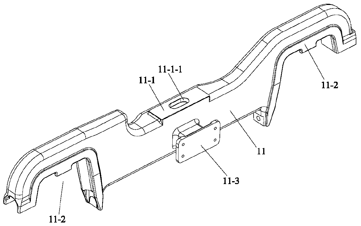
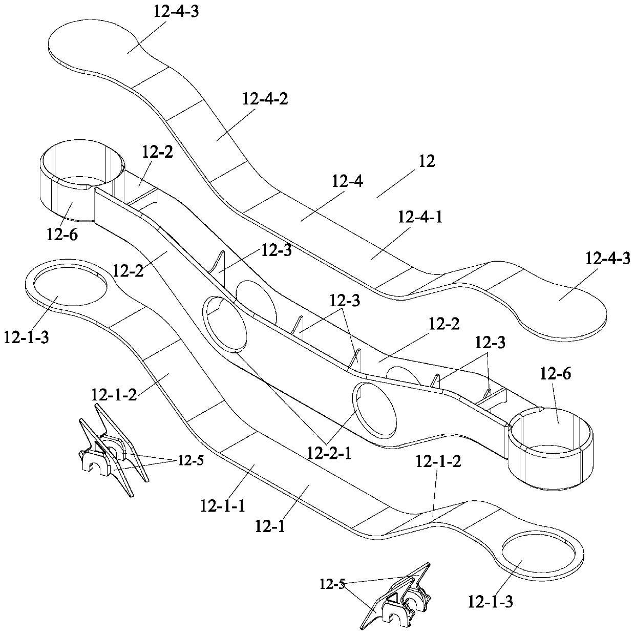
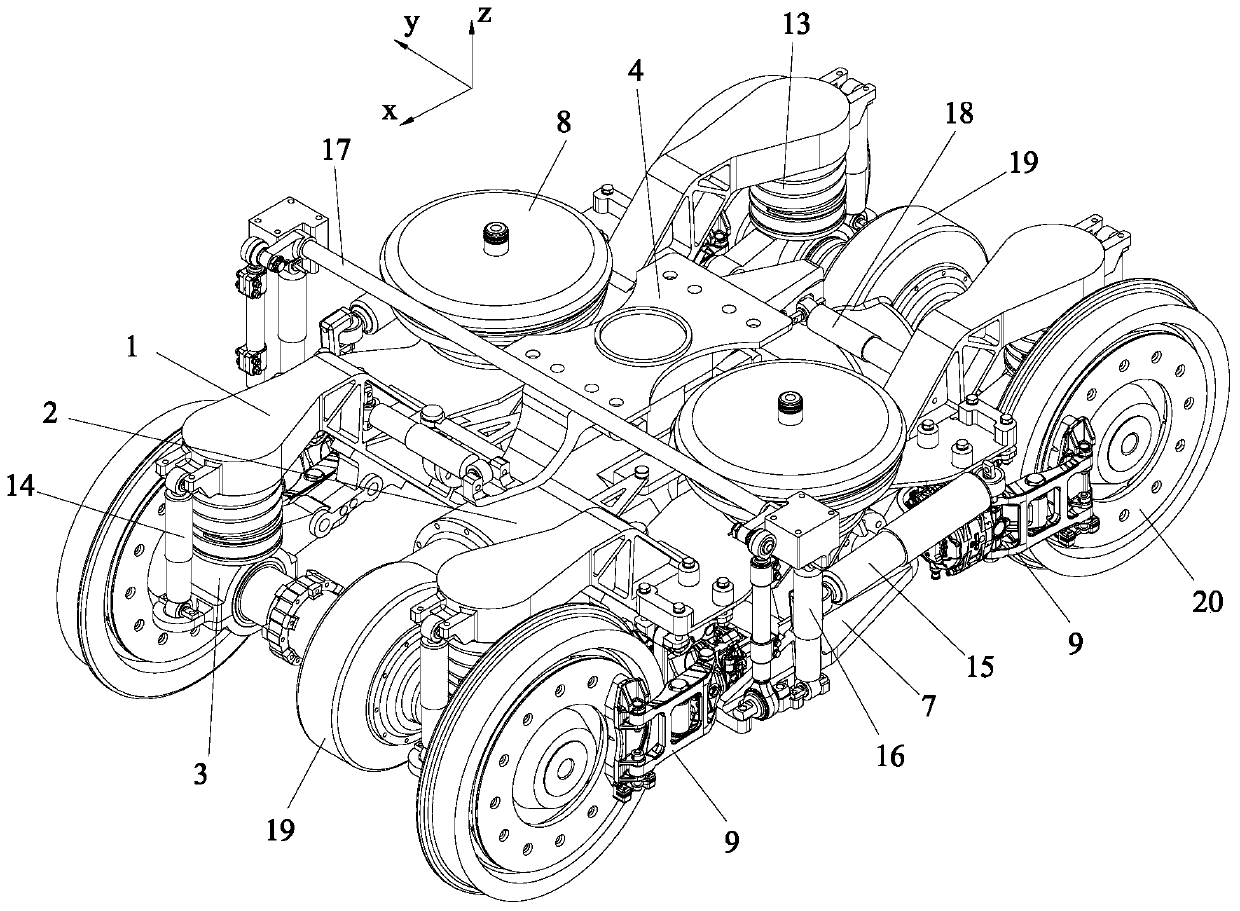
[0056] Such as Figure 3 to Figure 17 As shown, the motor longitudinally mounted modular power bogie of the present invention includes a bidirectional output shaft motor, two wheel sets 20, four brake caliper units 9, four primary steel springs 13, four primary vertical reducers Vibrator 14, two anti-snaking shock absorbers 15, two secondary vertical shock absorbers 16, two gear boxes 19, two secondary transverse shock absorbers 18 and two air springs 8, the device also includes Two forged side beams 1, longitudinal motor housing 2, four wheel sets built-in primary suspension axle box device 3, center traction seat mechanism 4, two side beam balance connecting rods 5, two combined connecting seats 7, Four housing side beam connecting columns 10, door-shaped anti-rolling torsion bar mechanism 17, traction seat fixing and vibration damping mechanism 6.

[005...


PUM


Abstract

The invention discloses a longitudinal motor type modular power bogie, and belongs to the field of longitudinal motor type railway vehicle bogie devices. The modular power bogie comprises a bidirectional output shaft motor, two wheel sets, four brake clamp units, four primary steel springs, four primary vertical shock absorbers, two anti-snaking shock absorbers, two secondary vertical shock absorbers, two gearboxes, two secondary transverse shock absorbers, two air springs, two forged piece side beams, a longitudinally-arranged motor shell, four wheel set built-in primary suspension axle box devices, a center traction seat mechanism, two side beam balance connecting rods, two combined connecting seats, four shell side beam connecting columns, an n-shaped anti-side-rolling torsion bar mechanism and a traction seat fixing and shock absorbing mechanism. According to the invention, the framework space can be greatly saved, the compact layout of the wheel set built-in primary suspension axle box devices can be implemented, the motor control program can be simplified, the electric energy utilization and conversion efficiency and the control efficiency can be improved, and the energy-saving and environment-friendly properties of the train can be enhanced.

Description

technical field [0001] The invention belongs to the field of motor longitudinally mounted rail vehicle bogie devices, in particular to a motor vertically mounted modularized power bogie. Background technique [0002] Rail vehicle bogies with traction motors are commonly called power bogies. Power bogies usually adopt a two-stage suspension system. The first suspension device is composed of a series of steel springs 13 and a series of vertical shock absorbers 14; Suspension device is made up of anti-snaking shock absorber 15, secondary vertical shock absorber 16, anti-rolling torsion bar 17 and secondary transverse shock absorber 18. Its design not only needs to comprehensively consider the structural strength and flexibility of the main body of the load-bearing frame, the effect of various auxiliary damping components such as anti-snaking shock absorbers, and the installation method of the braking mechanism, but also needs to be aimed at different According to the requireme...

Claims


Application Information

Patent Timeline
Patent Type & Authority Applications(China)
IPC IPC(8): B61C9/50B61F5/30B61F5/24B61F5/12B61F5/50
CPCB61C9/50B61F5/12B61F5/24B61F5/301B61F5/308B61F5/50
Inventor 吕常秀孙浩宴尹振坤
Owner CRRC CHANGCHUN RAILWAY VEHICLES CO LTD
Why Eureka
Try Eureka