
Manufacturing precision adjusting method based on zero-point positioner tool

A zero-point positioning and adjustment method technology, applied in the field of...

Active Publication Date: 2020-04-10
SHENYANG LIMING AERO-ENGINE GROUP CORPORATION
View PDF6 Cites 6 Cited by
  • Summary
  • Abstract
  • Description
  • Claims
  • Application Information

AI Technical Summary

Problems solved by technology

[0002] The tooling using the zero point locator is an indispensable type of fixture for the automatic machining production line. It has the advantages of accurate positioning, firm tightening, and convenient use. In use, multiple zero point locators are usually fixed on a base plate, which is convenient. Various machine tools or stations are used, but in the manufacturing process, the relative position accuracy of each zero locator is required to be very high. Usually at 20°C, the position accuracy of the positioning hole at the upper end of the zero locator is ≤φ0.015mm, facing With such a high technical requirement, the mounting holes corresponding to the zero locator on the foundation plate must be manufactured with precision boring equipment and a constant temperature manufacturing environment to ensure manufacturing accuracy, but such equipment and environments are difficult to meet at the same time, especially when there are many mounting holes. The precision of boring equipment is very discrete, and there are unavoidable assembly errors at the same time, which makes the accuracy of this type of tooling consistent and cannot be improved

Method used


Image

  • Manufacturing precision adjusting method based on zero-point positioner tool
  • Manufacturing precision adjusting method based on zero-point positioner tool
  • Manufacturing precision adjusting method based on zero-point positioner tool

Examples


Embodiment Construction

[0024] In order to better explain the present invention and facilitate understanding, the technical solutions and effects of the present invention will be described in detail below through specific implementation manners in conjunction with the accompanying drawings.

[0025] Such as Figure 5 As shown, in this embodiment, a manufacturing accuracy adjustment method based on the zero locator tooling of the present invention is used to adjust the precision of the tooling with five zero locators, which specifically includes the following steps:

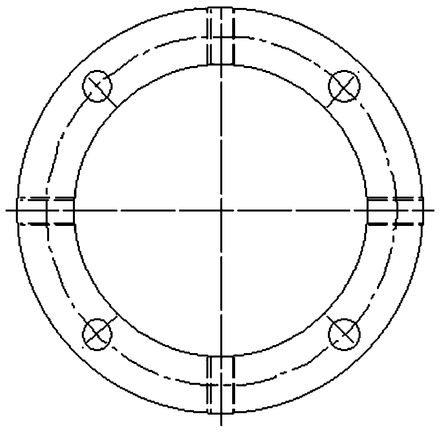
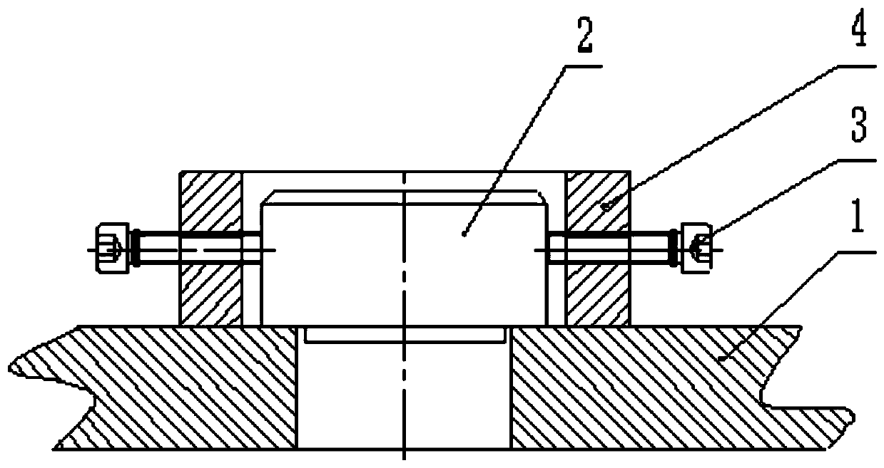
[0026] Step 1: If Figure 1-2 As shown, the adjustment ring is manufactured, and the inner diameter of the adjustment ring is larger than the outer diameter of the zero locator to ensure that there is a certain adjustment gap. In this embodiment, the gap between the inner hole of the adjustment and the positioning circle at the lower end of the zero locator is 2 mm; Four through holes are arranged, and the screws pass through the throug...


PUM


Abstract

The invention relates to a manufacturing precision adjusting method based on a zero-point positioner tool. A special adjusting ring with the inner diameter larger than the positioning circle of the zero-point positioner is manufactured and sleeves the positioning circle of the zero-point positioner, the middle mounting hole of a foundation plate is bored according to the positioning circle of thezero-point positioner, the diameters of other mounting holes are greater than the positioning circle of the zero-point positioner, through holes connected with the foundation plate are evenly distributed in the axial direction of the adjusting ring, threaded holes used for installing adjusting screws are evenly distributed in the outer circumference, the adjusting ring is used for adjusting the gap between the zero-point positioner and the mounting hole, the position of the zero-point positioner is measured in combination with a three-coordinate measuring machine, and correction is conducted if the position degree does not meet the tool technology requirement until reaching the requirement. According to the method, the three-coordinate measuring machine can online adjust the position of the zero-point positioner till the precision is the same as that of the three-coordinate measuring machine, the manufacturing process is simple, operation is easy and convenient, the positioning precision is high after adjustment and fixation, the capacity of manufacturing high-precision products can be achieved, and high generalization performance is achieved.

Description

technical field [0001] The invention belongs to the technical field, and in particular relates to a manufacturing precision adjustment method based on a zero point locator tool. Background technique [0002] The tooling using the zero point locator is an indispensable type of fixture for the automatic machining production line. It has the advantages of accurate positioning, firm tightening, and convenient use. In use, multiple zero point locators are usually fixed on a base plate, which is convenient. Various machine tools or stations are used, but in the manufacturing process, the relative position accuracy of each zero locator is required to be very high. Usually at 20°C, the position accuracy of the positioning hole at the upper end of the zero locator is ≤φ0.015mm, facing With such high technical requirements, the mounting holes corresponding to the zero locator on the foundation plate must be manufactured with precision boring equipment and a constant temperature manufa...

Claims


Application Information

Patent Timeline
Patent Type & Authority Applications(China)
IPC IPC(8): B23Q3/06B23Q17/00B23P15/00
CPCB23P15/00B23Q3/06B23Q17/00
Inventor 李想张强杨传勇彭会文孟宪国
Owner SHENYANG LIMING AERO-ENGINE GROUP CORPORATION
Learn More