Die machining fixing device with limiting function

A mold processing and fixing device technology, which is applied in the direction of metal processing equipment, forming tools, manufacturing tools, etc., can solve the problems of lower pass rate of workpieces, inaccurate stamping workpieces, etc.

Inactive Publication Date: 2020-04-10
吴中区甪直奥顿自动化设备厂
View PDF0 Cites 0 Cited by
  • Summary
  • Abstract
  • Description
  • Claims
  • Application Information

AI Technical Summary

Problems solved by technology

[0003] At present, in the mold processing process, the mold needs to be limited to ensure the accuracy of mold processing and the pass rate of component manufacturing. In the existing devices for mold processing and fixing with a limit function, due to the When the stamping process is carried out in the mold, if there is no fastening treatment between the workpiece and the mold, there will be a relative slip between the two positions due to the shock in the stamping and mold making process, resulting in inaccurate stamping of the workpiece. The qualification rate of the workpiece is greatly reduced. Therefore, a fixture with a limit function for mold processing is of great practical value.

Method used


Image

  • Die machining fixing device with limiting function
  • Die machining fixing device with limiting function
  • Die machining fixing device with limiting function

Examples


Embodiment Construction

[0017] The following will clearly and completely describe the technical solutions in the embodiments of the present invention with reference to the accompanying drawings in the embodiments of the present invention. Obviously, the described embodiments are only some, not all, embodiments of the present invention. Based on the embodiments of the present invention, all other embodiments obtained by persons of ordinary skill in the art without making creative efforts belong to the protection scope of the present invention.

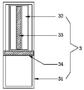
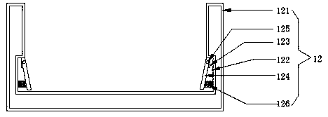
[0018] see figure 1 , the present invention provides a technical solution: a fixing device for mold processing with a limit function, including a base 1, a universal wheel 2 is provided at the bottom of the base 1, and support plates 3 are provided on the left and right sides of the top of the base 1, two groups The top of the support plate 3 is provided with a mounting plate 4, the right side of the bottom of the mounting plate 4 is provided with a first elec...


PUM


Abstract

The invention discloses a die machining fixing device with a limiting function and belongs to the technical field of die machining devices. The die machining fixing device with the limiting function comprises a base. The bottom of the base is provided with universal wheels. The left side and the right side of the top of the base are both provided with supporting plates. The tops of the two groupsof supporting plates are both provided with an installation plate. A first electric telescopic rod is arranged on the right side of the bottom of the installation plate. A second electric telescopic rod is arranged on the left side of the bottom of the installation plate. The bottoms of the first electric telescopic rod and the second electric telescopic rod are both provided with fixing blocks. The opposite faces of the two fixing blocks are both connected with an upper die. The end, far away from of the upper die, of each fixing block is provided with a smooth column. The outer peripheries of the smooth columns are provided with slider sleeves in a surrounding manner. The top of the base is provided with a lower die. The left side and the right side of the outer periphery of the lower die are both provided with connection plates. The die machining fixing device with the limiting function achieves limiting treatment in the die machining process and can conduct clamping treatment on components in the die machining process at the same time.

Description

technical field [0001] The invention relates to the technical field of mold processing equipment, in particular to a fixing device for mold processing with a position limiting function. Background technique [0002] Mold Making refers to the processing of forming and billet tools, and also includes shearing dies and die-cutting dies. Usually, the mold consists of two parts, the upper mold and the lower mold. The steel plate is placed between the upper and lower molds, and the material is formed under the action of the press. When the press is opened, the workpiece determined by the shape of the mold is obtained or the corresponding waste is removed. Workpieces as small as electronic connectors and as large as automotive dashboards can be molded. Progressive die refers to a set of molds that can automatically move the workpiece from one station to another, and obtain formed parts at the last station. Mold processing technology includes: cutting die, punching die, composite...

Claims


Application Information

Patent Timeline
IPC IPC(8): B21D37/12B21D22/02B21D37/04
CPCB21D22/02B21D37/04B21D37/12
Inventor 陈学究
Owner 吴中区甪直奥顿自动化设备厂
Why Eureka
Try Eureka