Electromechanical automatic controller of revolving door
An automatic controller and revolving door technology, which is applied in the field of revolving doors, can solve the problems of load-bearing wheel wear and revolving door turning laborious, and achieve the effect of reducing the burden
- Summary
- Abstract
- Description
- Claims
- Application Information
AI Technical Summary
Problems solved by technology
Method used
Image

Examples
Embodiment 1
[0029] This embodiment provides an electromechanical automatic controller for a revolving door, and implements the present invention through basic necessary technical features to solve the problems raised in the technical background section of this application document.
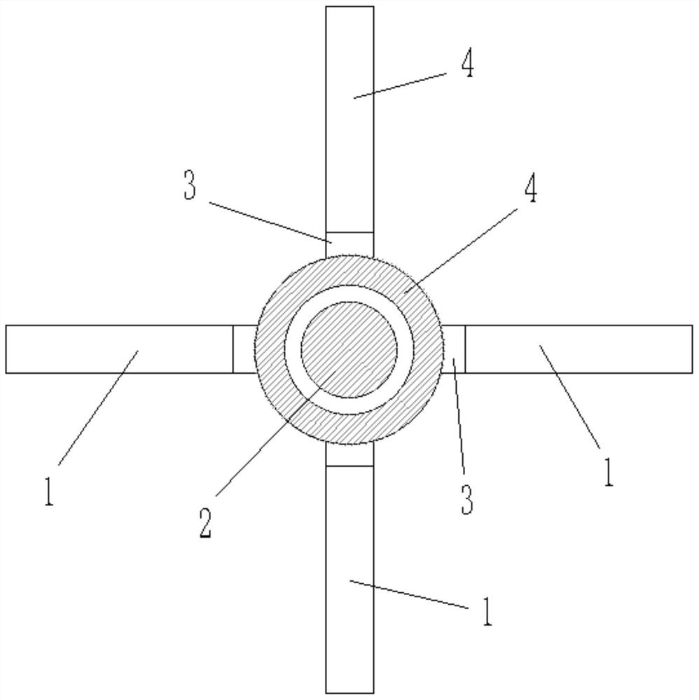
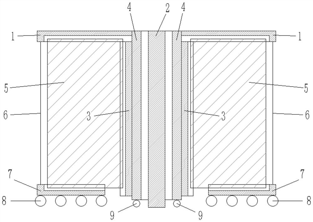
[0030] Specifically, such as Figure 1-2 As shown, the embodiment of the present invention provides an electromechanical automatic controller for a revolving door, including a door shaft 2, a sleeve 4 that rotates around the door shaft 2 is sheathed on the outside of the door shaft 2, and the upper end of the sleeve 4 is along the Its circumferential direction is respectively fixed with a plurality of horizontal fixing grooves 1 with opening downwards, and a vertical fixing groove 3 opening outwards is arranged below the horizontal fixing grooves 1, and the vertical fixing grooves 3 are fixed on the outer wall of the sleeve 4 Above, the outer end of the horizontal fixing groove 1 is connected with an upper st...
Embodiment 2
[0034] This example is based on Example 1 and optimizes the implementation in Example 1, so that this example is more stable and has better performance during operation, but it is not limited to the one described in this example implementation.
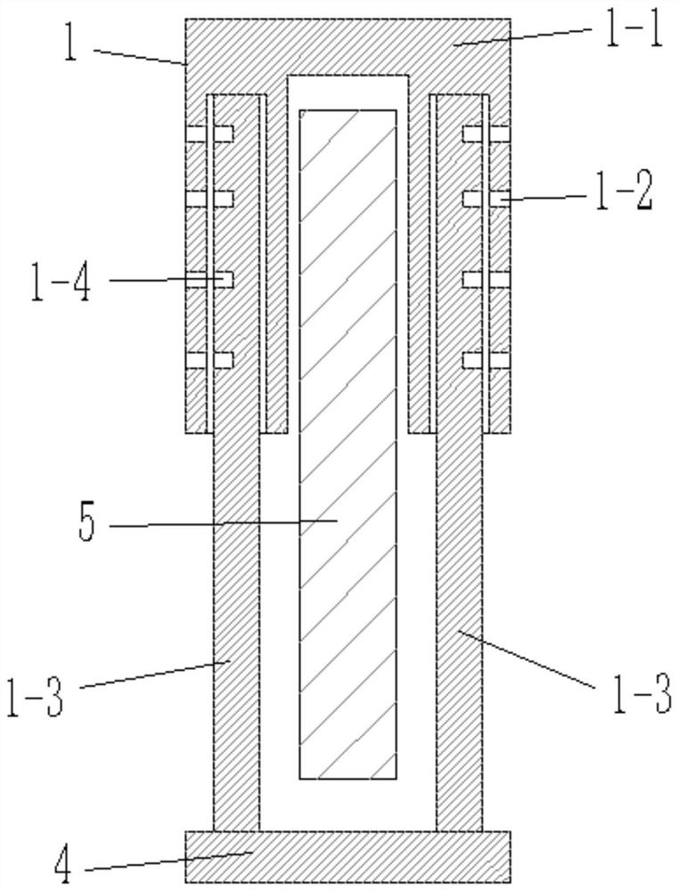
[0035] Specifically, such as Figure 1-3 As shown, in this embodiment, a groove with an opening downward is provided under the upper stopper, and a connecting shaft is arranged in the groove, and one end of the connecting shaft is connected to the groove wall on one side of the groove through a torsion spring. The other end of the connecting shaft is hingedly connected to the groove wall on the other side of the groove through the first bearing, and the rope 6 is fixed on the shaft of the connecting shaft.
[0036]In this embodiment, the horizontal fixing groove 1 and the lower fixing groove 7 are connected together by the rope 6, and at the same time, under the action of the torsion spring, the connecting shaft generates a winding f...
Embodiment 3
[0041] This example is based on Example 1 and optimizes the implementation in Example 1, so that this example is more stable and has better performance during operation, but it is not limited to the one described in this example implementation.
[0042] Specifically, such as Figure 1-5 As shown, in this embodiment, the drive mechanism includes a connection plate 12 fixed on the top of the sleeve 4, the connection plate 12 is located directly above the sleeve 4, and the center of the connection plate 12 passes through the upper connecting rod 17 is connected with driven gear 16, and driven gear 16 is meshed with driving gear 13, and the output shaft of driving gear 13 and servomotor 14 is connected by key.
[0043] When the drive mechanism was working, the servomotor 14 worked, and the output shaft of the servomotor 14 rotated, thereby causing the driving gear 13 to rotate. At this time, because the driven gear 16 meshed with the driving gear 13, the driven gear 16 rotates, ...
PUM
 Abstract
Description
Claims
Application Information
 - R&D
- Intellectual Property
- Life Sciences
- Materials
- Tech Scout
- Unparalleled Data Quality
- Higher Quality Content
- 60% Fewer Hallucinations
Browse by: Latest US Patents, China's latest patents, Technical Efficacy Thesaurus, Application Domain, Technology Topic, Popular Technical Reports.
© 2025 PatSnap. All rights reserved.Legal|Privacy policy|Modern Slavery Act Transparency Statement|Sitemap|About US| Contact US: help@patsnap.com