A diesel engine flywheel housing
A diesel engine and flywheel housing technology, which is applied to the frame of the engine, supporting machines, mechanical equipment, etc., can solve the problems of inconvenient installation and use, large overall weight, and poor rigidity of the workpiece, so as to achieve convenient removal and replacement and ensure heat dissipation effect , the effect of dispersing stress
- Summary
- Abstract
- Description
- Claims
- Application Information
AI Technical Summary
Problems solved by technology
Method used
Image


Examples
Embodiment 1
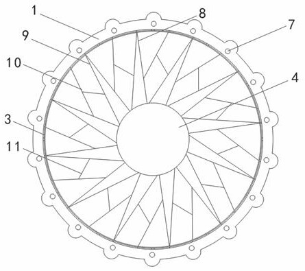
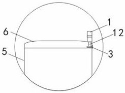
[0023] A diesel engine flywheel housing, comprising a flywheel housing, the flywheel housing includes a bottom surface 5 and a side wall 6 surrounding the bottom surface 5, the rear end of the side wall 6 is connected to the bottom surface 5, the bottom surface 5 and the side wall 6 Integral molding, the bottom surface 5 and the side wall 6 form a cavity for accommodating the flywheel, the center of the bottom surface 5 is provided with a crankshaft center hole 4, and the front periphery of the side wall 6 is provided with a circle of mounting lugs 1, and the mounting lugs 1 are evenly arranged along the circumferential direction There are several threaded holes 7, the lower half of the side wall 6 is provided with a heat dissipation window 2, and the front end of the flywheel housing is provided with a circle of dust-proof net positioning ring 3, and the dust-proof net positioning ring 3 is arranged in the cavity, and is connected with the crankshaft center hole 4 Concentric s...
Embodiment 2
[0028]A diesel engine flywheel housing, comprising a flywheel housing, the flywheel housing includes a bottom surface 5 and a side wall 6 surrounding the bottom surface 5, the rear end of the side wall 6 is connected to the bottom surface 5, the bottom surface 5 and the side wall 6 Integral molding, the bottom surface 5 and the side wall 6 form a cavity for accommodating the flywheel, the center of the bottom surface 5 is provided with a crankshaft center hole 4, and the front periphery of the side wall 6 is provided with a circle of mounting lugs 1, and the mounting lugs 1 are evenly arranged along the circumferential direction There are several threaded holes 7, the lower half of the side wall 6 is provided with a heat dissipation window 2, and the front end of the flywheel housing is provided with a circle of dust-proof net positioning ring 3, and the dust-proof net positioning ring 3 is arranged in the cavity, and is connected with the crankshaft center hole 4 Concentric se...
Embodiment 3
[0033] A diesel engine flywheel housing, comprising a flywheel housing, the flywheel housing includes a bottom surface 5 and a side wall 6 surrounding the bottom surface 5, the rear end of the side wall 6 is connected to the bottom surface 5, the bottom surface 5 and the side wall 6 Integral molding, the bottom surface 5 and the side wall 6 form a cavity for accommodating the flywheel, the center of the bottom surface 5 is provided with a crankshaft center hole 4, and the front periphery of the side wall 6 is provided with a circle of mounting lugs 1, and the mounting lugs 1 are evenly arranged along the circumferential direction There are several threaded holes 7, the lower half of the side wall 6 is provided with a heat dissipation window 2, and the front end of the flywheel housing is provided with a circle of dust-proof net positioning ring 3, and the dust-proof net positioning ring 3 is arranged in the cavity, and is connected with the crankshaft center hole 4 Concentric s...
PUM
| Property | Measurement | Unit |
|---|---|---|
| thickness | aaaaa | aaaaa |
| elastic modulus | aaaaa | aaaaa |
| density | aaaaa | aaaaa |
Abstract
Description
Claims
Application Information
 - R&D
- Intellectual Property
- Life Sciences
- Materials
- Tech Scout
- Unparalleled Data Quality
- Higher Quality Content
- 60% Fewer Hallucinations
Browse by: Latest US Patents, China's latest patents, Technical Efficacy Thesaurus, Application Domain, Technology Topic, Popular Technical Reports.
© 2025 PatSnap. All rights reserved.Legal|Privacy policy|Modern Slavery Act Transparency Statement|Sitemap|About US| Contact US: help@patsnap.com