Automatic control device for hydrogen fluoride supply

An automatic control device and hydrogen fluoride technology, applied in the field of electrolytic fluorine production, can solve the problems of low automation level of electrolytic cells, and achieve the effects of eliminating the possibility of contact, continuous feeding and reducing loss

Inactive Publication Date: 2020-04-07
中核二七二铀业有限责任公司
View PDF8 Cites 1 Cited by
  • Summary
  • Abstract
  • Description
  • Claims
  • Application Information

AI Technical Summary

Problems solved by technology

[0006] Due to the high probability of operators being exposed to AHF in the traditional technical solution, the automation level of the electrolyzer is low, and there are potential safety hazards on site

Method used


Image

  • Automatic control device for hydrogen fluoride supply

Examples


Embodiment Construction

[0037] The technical solution of the present invention will be described in detail below in conjunction with the accompanying drawings and specific embodiments.

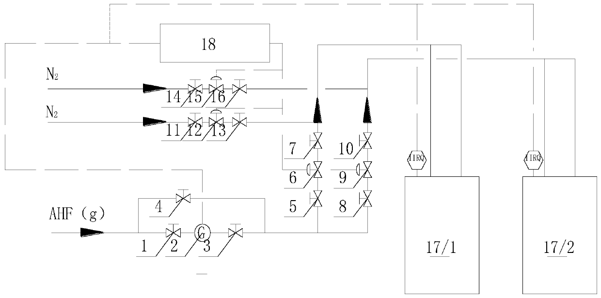
[0038] Such as figure 1 Shown, the automatic control device of a kind of hydrogen fluoride feeding of the present invention, this device comprises:

[0039] Stop valve one 1, mass flow meter 2, stop valve two 3, stop valve three 4, stop valve four 5, pneumatic valve one 6, stop valve five 7, stop valve six 8, pneumatic valve two 9, stop valve seven 10, Ball valve three 11, solenoid valve two 12, ball valve one 14, solenoid valve one 15, ball valve two 16, electrolytic tank one 171, electrolytic tank two 172, DCS automatic control module 18;

[0040] Set shut-off valve 1, mass flow meter 2, shut-off valve 2 and 3 sequentially from the hydrogen fluoride inlet;

[0041] A shut-off valve 3 4 is arranged in parallel between the shut-off valve 1, the mass flow meter 2, and the shut-off valve 2 3;

[0042] After the cut-...


PUM


Abstract

The invention belongs to the technical field of electrolytic fluorine production, and particularly relates to an automatic control device for hydrogen fluoride supply. The device comprises a first stop valve 1, a mass flow meter 2, a second stop valve 3, a third stop valve 4, a fourth stop valve 5, a first pneumatic valve 6, a fifth stop valve 7, a sixth stop valve 8, a second pneumatic valve 9, aseventh stop valve 10, a third ball valve 11, a second electromagnetic valve 12, a first ball valve 14, a first electromagnetic valve 15, a second ball valve 16, a first electrolytic cell 171, a second electrolytic cell 172 and a DCS automatic control module 18. By using the device, the loss of a hydrogen fluoride material can be reduced, the process parameter stability of the electrolytic cellscan be improved, and the acidity can be stabilized within the range of 38-42%. The service life of the carbon plates of the electrolytic cells can be prolonged by more than 30-50%. Continuous feedingof the electrolytic cells can be realized.

Description

technical field [0001] The invention belongs to the technical field of electrolytic fluorine production, and in particular relates to an automatic control device for feeding hydrogen fluoride. Background technique [0002] In the field of electrolytic fluorine production, there are two main technologies for hydrogen fluoride feeding: centralized and individual feeding. In production practice, conventional selection (gas phase or liquid phase centralized feeding and separate feeding) is used to achieve the purpose of material balance and stable operation during the operation of the electrolyzer. [0003] Among the above methods, the AHF centralized feeding material measurement is difficult, and the stable operation control is difficult, but the number of centralized feeding equipment is small, and the material centralized safety factor is large, which is most suitable for automatic control. [0004] In conventional industrial production, the AHF centralized feeding of the el...

Claims


Application Information

Patent Timeline
IPC IPC(8): C25B15/08C25B1/24
CPCC25B1/245C25B15/08
Inventor 付文俊胡锦明江志文王超李帅王剑卫罗一峰
Owner 中核二七二铀业有限责任公司
Why Eureka
Try Eureka