Gas suspending device
An air suspension and air chamber technology, applied in the field of air suspension, can solve the problems of noise pollution, high operating power of the compressor, large gas consumption, etc., achieve good effect, solve the effect of low operating speed and high load efficiency
- Summary
- Abstract
- Description
- Claims
- Application Information
AI Technical Summary
Problems solved by technology
Method used
Image

Examples
Embodiment 1
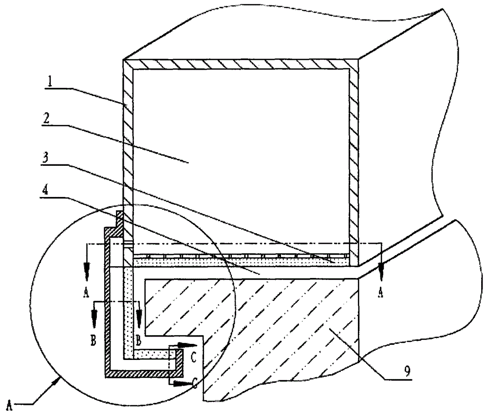
[0045] figure 1 A schematic structural diagram of the air levitation device in Example 1 of the present invention is shown. Such as figure 1As shown, the air suspension device in this embodiment includes a leg 1 and a leg air chamber 2 inside the leg 1 . The leg part 1 includes a suspended seepage surface 3 formed of porous material, and the suspended seepage surface 3 faces the external running surface 9 on which the air suspension device operates. When the leg air chamber 2 is filled with compressed gas from the air supply equipment, the pressure in the leg air chamber 2 is greater than the external pressure, and the porous material produces a perspiration seepage effect under the action of the compressed gas, so that the suspended seepage surface 3 and A suspended air film 4 is formed in the gap between the outer running surfaces 9 . Since the coefficient of friction between the suspended air film 4 and the outer running surface 9 is very small, the air suspension device...
Embodiment 2
[0052] When the outer running surface is a guide rail, that is, when the guide rail is used to carry the air suspension device, in order to prevent the air suspension device from turning over, the air suspension device also includes a baffle parallel to the side of the guide rail. However, if the baffle plate rubs against the side of the guide rail, not only will the running speed of the air suspension device be reduced, but the heat generated by the friction will also bring potential safety hazards. In order to avoid this problem, the air suspension device of this embodiment further includes a baffle air film located between the baffle and the side of the guide rail.
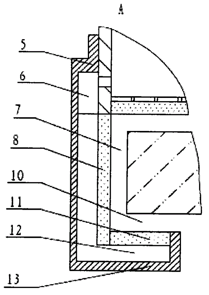
[0053] image 3 yes figure 1 Partial enlarged view in . Such as image 3 As shown, on the basis of the first embodiment, the air suspension device of this embodiment adds a baffle 5 connected to the side of the leg 1 and extending toward the ground. Moreover, the air suspension device also includes a side a...
Embodiment 3
[0059] In order to prevent the air levitation device from detaching from the guide rail, this embodiment may further include a hook in the air levitation device on the basis of embodiment 1 or embodiment 2. Such as image 3 As shown, the hook 13 in this embodiment is L-shaped at right angles. Wherein, the L-shaped first plane extends along the running direction of the air suspension device, and is parallel to the suspension seepage surface 3 and perpendicular to the baffle 5 . The gap between the first plane and the suspension seepage surface 3 accommodates guide rails for the operation of the air suspension device. The L-shaped second plane is located below the guide rail, extends along the running direction of the air suspension device, and is perpendicular to the first plane and parallel to the baffle 5 .
[0060] The air suspension device of this embodiment further includes: a hook seepage surface 11 comprising porous material, the hook seepage surface 11 is parallel to ...
PUM
| Property | Measurement | Unit |
|---|---|---|
| Angle | aaaaa | aaaaa |
Abstract
Description
Claims
Application Information
 - R&D
- Intellectual Property
- Life Sciences
- Materials
- Tech Scout
- Unparalleled Data Quality
- Higher Quality Content
- 60% Fewer Hallucinations
Browse by: Latest US Patents, China's latest patents, Technical Efficacy Thesaurus, Application Domain, Technology Topic, Popular Technical Reports.
© 2025 PatSnap. All rights reserved.Legal|Privacy policy|Modern Slavery Act Transparency Statement|Sitemap|About US| Contact US: help@patsnap.com