
Air-cooled axle-controlled traction inversion power unit with double-sided heat dissipation

A power unit, double-sided heat dissipation technology, applied in the direction of output power conversion device, AC power input conversion to DC power output, electrical components, etc., can solve the problem of inability to install cooling tower water cooling system, reduced heat dissipation effect of devices, and occupied size Large and other problems, to achieve the effect of improving the anti-fault ability, high adhesion utilization rate, and less traction loss

Pending Publication Date: 2020-04-03
XIAN YONGDIAN ELECTRIC
View PDF5 Cites 2 Cited by
  • Summary
  • Abstract
  • Description
  • Claims
  • Application Information

AI Technical Summary

Problems solved by technology

However, due to the space limitation of diesel locomotives, it is impossible to install huge water cooling systems such as cooling towers, and its traction power units often adopt air cooling
The traction inverter power unit that adopts air-cooled heat dissipation method only has the IGBT single-sided layout method, that is, all power devices are arranged on the substrate of a heat sink, the overall structure occupies a large size, and the traction inverter power unit is installed on the side of the air duct. On one side, the cooling air flows through all the power devices from the inlet to the outlet, and the cooling air continuously takes away the heat passing through the devices, the temperature of the air keeps rising, and the heat dissipation effect of the devices at the far end of the inlet is greatly reduced

Method used


Image

  • Air-cooled axle-controlled traction inversion power unit with double-sided heat dissipation
  • Air-cooled axle-controlled traction inversion power unit with double-sided heat dissipation
  • Air-cooled axle-controlled traction inversion power unit with double-sided heat dissipation

Examples


Embodiment

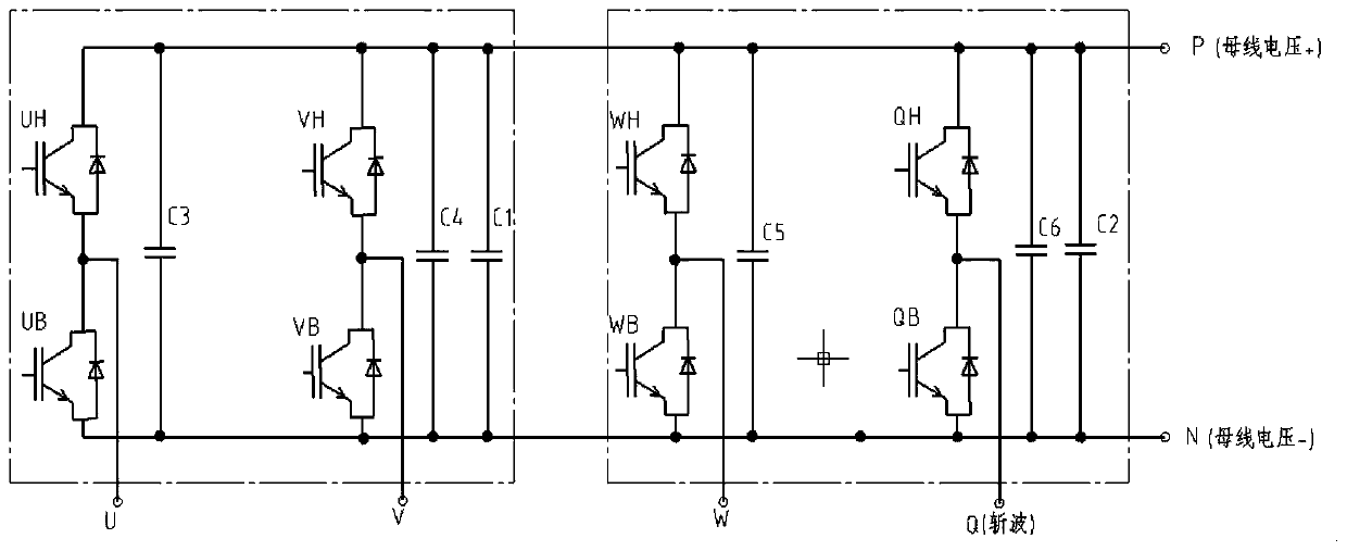
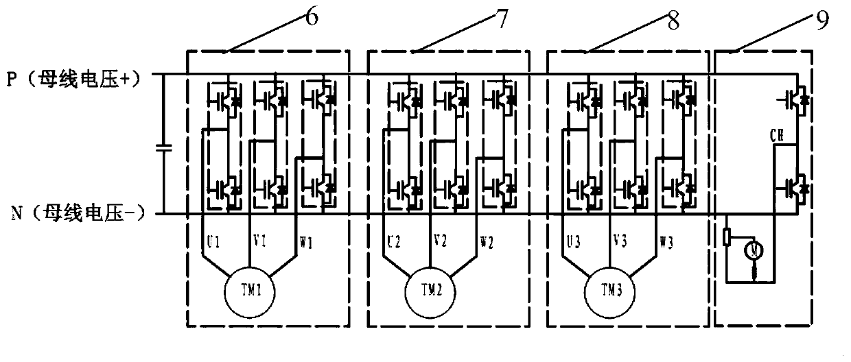
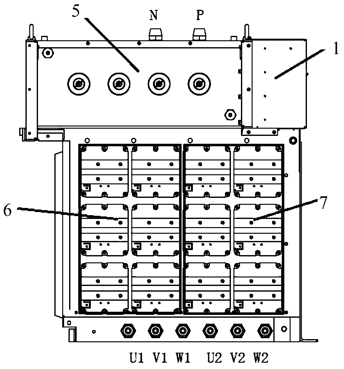
[0030] see Figure 2-6 As shown, the present invention provides an air-cooled shaft-controlled traction inverter power unit with double-sided heat dissipation, including: a main body of the power unit and a supporting frame installed outside the main body of the power unit, the front surface of the supporting frame is from top to The drive control box 1 and the main air duct 2 are distributed below, and the left and right sides of the support frame are correspondingly installed with a left cover 3 and a right cover 4;

[0031] The top of the main body of the power unit is provided with supporting capacitors 5, and the supporting capacitors 5 are installed on the top of the supporting frame, and each supporting capacitor 5 is connected to a capacitor busbar, and the P / N terminal on the capacitor busbar provides DC power for the inverter circuit; A heat pipe radiator is respectively installed on both sides of the main air duct 2, and one end of the heat pipe radiator extends int...


PUM


Abstract

The invention belongs to the technical field of bullet train locomotive traction systems and relates to an air-cooled axle-controlled traction inversion power unit with double-sided heat dissipation.An original mode that a frame control type three-phase inverter circuit is used for pulling three motors is replaced by a mode that a shaft control type three-phase inverter circuit pulls three motors. On the premise that the installation size of an original frame control type traction inversion power unit is met, three three-phase inversion units, a chopping unit and a direct current bus supportcapacitor are integrated on one power module, so that the power conversion function of one three-phase inversion unit and one chopping unit in the original frame control traction inversion power unitis realized, the system redundancy is improved, and the fault resistance is enhanced; and meanwhile, the heat pipe radiators are additionally arranged on the two sides of the main body air duct, so that the double-sided layout mode of the IGBT in one power unit in an air-cooled heat dissipation mode is realized, the heat dissipation of the IGBT is more uniform, the length of the radiators is reduced, the space utilization rate of a locomotive is improved, and finally, the cooling effect of the power unit is improved.

Description

technical field [0001] The invention belongs to the technical field of locomotive traction systems, and relates to an axle-controlled traction inverter power unit of a diesel locomotive, in particular to an air-cooled axle-controlled traction inverter power unit with double-sided heat dissipation. Background technique [0002] At present, the existing AC drive diesel locomotives usually have two power configuration modes: frame control and axle control. The frame control configuration method is that one traction inverter drives all the motors under the corresponding bogie to run. In this power configuration method, the system is greatly affected by the wheel diameter, and the adhesion utilization rate is low. When the inverter fails , the locomotive will lose half of its power, the system has poor anti-failure ability and low redundancy. The shaft control configuration mode is that one inverter alone drives one motor to run. Compared with the frame control configuration mod...

Claims


Application Information

Patent Timeline
Patent Type & Authority Applications(China)
IPC IPC(8): H02P27/06H02M7/00H05K7/20
CPCH02P27/06H02M7/003H05K7/20909
Inventor 杨春宇陈彦肖陈宏张丹
Owner XIAN YONGDIAN ELECTRIC
Learn More