Transformer fireproof device with heat dissipation function

A fire prevention device and transformer technology, applied in the field of transformers, can solve the problems of reducing the service life of transformers, causing fires, property damage, etc., and achieve the effect of reducing temperature and reducing heat

Active Publication Date: 2020-04-03
ZTT TRANSFORMER CO LTD
View PDF11 Cites 1 Cited by
  • Summary
  • Abstract
  • Description
  • Claims
  • Application Information

AI Technical Summary

Problems solved by technology

[0003] Many transformers in the prior art are installed in the transformer box. Installing the transformer in the transformer box can increase safety and aesthetics, but the heat dissipation will be poor, and the transformer will generate a lot of heat during operation. If If the transformer is not dissipated, the service life of the transformer will be reduced if it is used for a long time. In severe cases, it may cause a fire, which brings economic losses to people and is not convenient to use. The box-type transformer in the prior art does not have an automatic fire extinguishing device, and a fire occurs in the transformer. It is difficult to extinguish the fire in time, causing life threat and property damage

Method used


Image

  • Transformer fireproof device with heat dissipation function
  • Transformer fireproof device with heat dissipation function
  • Transformer fireproof device with heat dissipation function

Examples


Embodiment 1

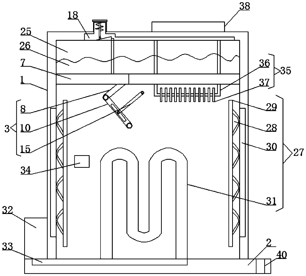
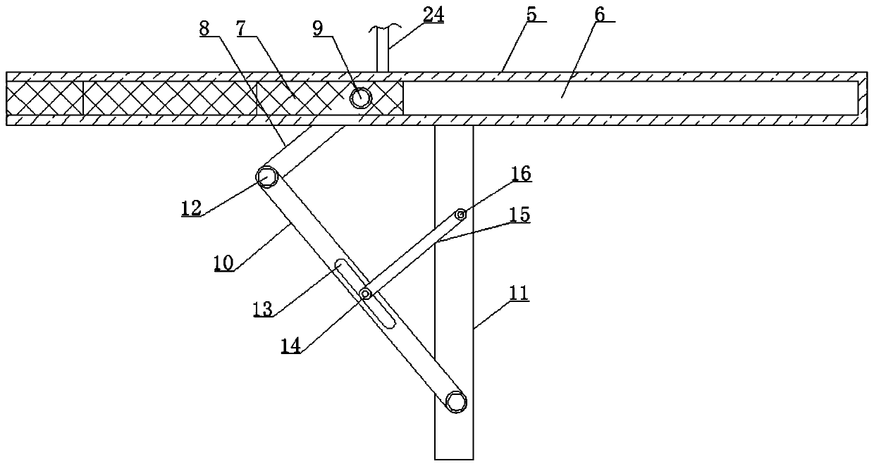
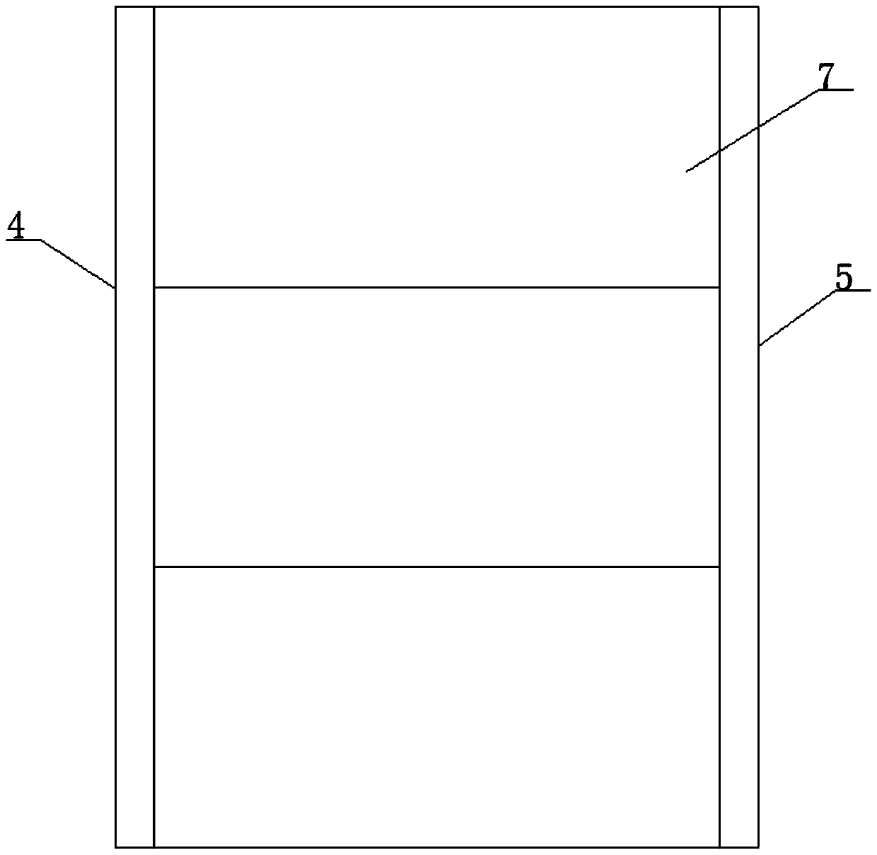
[0028] Such as Figure 1-4 As shown, the transformer fire protection device with heat dissipation function according to the embodiment of the present invention includes a transformer box 1 and a mounting seat 2 located at the bottom of the transformer box 1, and the transformer box 1 is a cavity structure with a lateral opening , and the top of the transformer box 1 is provided with a fireproof mechanism 3, and the fireproof mechanism 3 includes a connection block 1 4 and a connection block 2 5 arranged laterally symmetrically on both sides of the transformer box 1, A side of the connecting block one 4 and the connecting block two 5 close to each other is provided with a chute 6, and the transformer box 1 is provided with a telescopic plate 7 connected with two groups of the chute 6, and the The bottom end of the telescopic plate 7 is provided with an obliquely arranged movable rod 8, and the movable rod 8 is connected with the described telescopic plate 7 by a roller 9, and t...

Embodiment 2

[0030] Such as Figure 1-4As shown, the heat dissipation mechanism 27 includes heat dissipation strips 28 located on both sides of the inner wall of the transformer box body 1, and the sides of the heat dissipation strips 28 that are close to each other are provided with matching heat dissipation plates 29, and the transformer box body There are heat collecting chambers 30 on both sides of the inner wall of 1, wherein the heat dissipation mechanism 27 also includes a cooling pipe 31 located on one side of the inner wall of the transformer box 1, the cooling pipe 31 is arranged in a curved shape, and the transformer box 1 and at the top of the mounting base 2 is provided with a cooling box 32 , and the cooling box 32 is connected to the cooling pipe 31 through a conduit 33 . It is not difficult to see from the above design that through the coordinated design of the heat dissipation mechanism 27, the height in the transformer box 1 is absorbed by the heat dissipation belt 28 and...

Embodiment 3

[0032] Such as Figure 1-4 As shown, a temperature sensor 34 is provided on one side of the transformer box 1 and on the side of the installation frame 11, and a temperature sensor 34 is provided on the bottom of the transformer box 1 and on the connecting block one 4 Heat-absorbing mechanism 35, described heat-absorbing mechanism 35 comprises the radiating pipe 36 that is positioned at the bottom end of described connection block 4, and described radiating pipe 36 is provided with some evenly distributed heat-collecting fins 37, and described radiating pipe 36 is U-like Type structure, and the heat dissipation pipe 36 extends to the top of the transformer box 1 with a fan 38, the top of the transformer box 1 is provided with a protective cover sleeved on the fan 38, and the heat dissipation Both the tube 36 and the heat collecting fins 37 are hollow structures, and the interior of the heat dissipation pipe 36 communicates with the interior of the heat collecting fins 37 . It...


PUM


Abstract

The invention discloses a transformer fireproof device with a heat dissipation function. The transformer fireproof device comprises a transformer box body and a mounting base located at the bottom endof the transformer box body. The transformer box body is of a cavity structure with a lateral opening. A fireproof mechanism is arranged at the top end in the transformer box body; the fireproof mechanism comprises a first connecting block and a second connecting block which are transversely arranged and symmetrically arranged on the two sides in the transformer box body, chutes are formed in thesides, close to each other, of the first connecting block and the second connecting block, a telescopic plate connected with the two chutes is arranged in the transformer box body, and an obliquely-arranged movable rod is arranged at the bottom end of the telescopic plate. The transformer fireproof device has the beneficial effects that when the telescopic plate stretches out and draws back, sandcan leak out of the bottom of a compartment, fire is extinguished, and the fireproof effect is achieved; the interior of the transformer box body communicates with the outside, so that explosion is prevented; and due to the design of a heat dissipation mechanism, the temperature generated by the heating body is reduced, and heat in the transformer can be reduced.

Description

technical field [0001] The invention relates to the technical field of transformers, in particular to a transformer fire protection device with heat dissipation function. Background technique [0002] The transformer is a device that uses the principle of electromagnetic induction to change the AC voltage. The main components are the primary coil, the secondary coil and the iron core (magnetic core). The main functions are: voltage conversion, current conversion, impedance conversion, isolation, voltage stabilization (magnetic Saturated transformers), etc., can be divided into: power transformers and special transformers (electric furnace transformers, rectifier transformers, power frequency test transformers, voltage regulators, mining transformers, audio transformers, intermediate frequency transformers, high frequency transformers, impact transformers, instrument Use transformers, electronic transformers, reactors, transformers, etc.), circuit symbols often use T as the b...

Claims


Application Information

Patent Timeline
Patent Type & Authority Applications(China)
IPC IPC(8): H01F27/40H01F27/02H01F27/16H01F27/22A62C3/16A62C37/40A62C37/42
CPCA62C3/16A62C37/40A62C37/42H01F27/025H01F27/16H01F27/22H01F27/402H01F2027/406
Inventor 倪卫荣
Owner ZTT TRANSFORMER CO LTD
Why Eureka
Try Eureka