
Soldering lug allowance supporting device for quick processing and welding of curved waveguide

An auxiliary device and curved waveguide technology, which is applied in the field of curved waveguides, can solve the problems of difficult removal of redundant objects, thin-walled waveguide weld seams, failure to meet product requirements, etc., to achieve time-saving and labor-saving processing, good welding effect, and avoid The effect of movement

Inactive Publication Date: 2020-04-03
南京驰韵科技发展有限公司
View PDF0 Cites 0 Cited by
  • Summary
  • Abstract
  • Description
  • Claims
  • Application Information

AI Technical Summary

Problems solved by technology

The old-fashioned overall processing method is difficult and costly, so the split welding processing method is more important
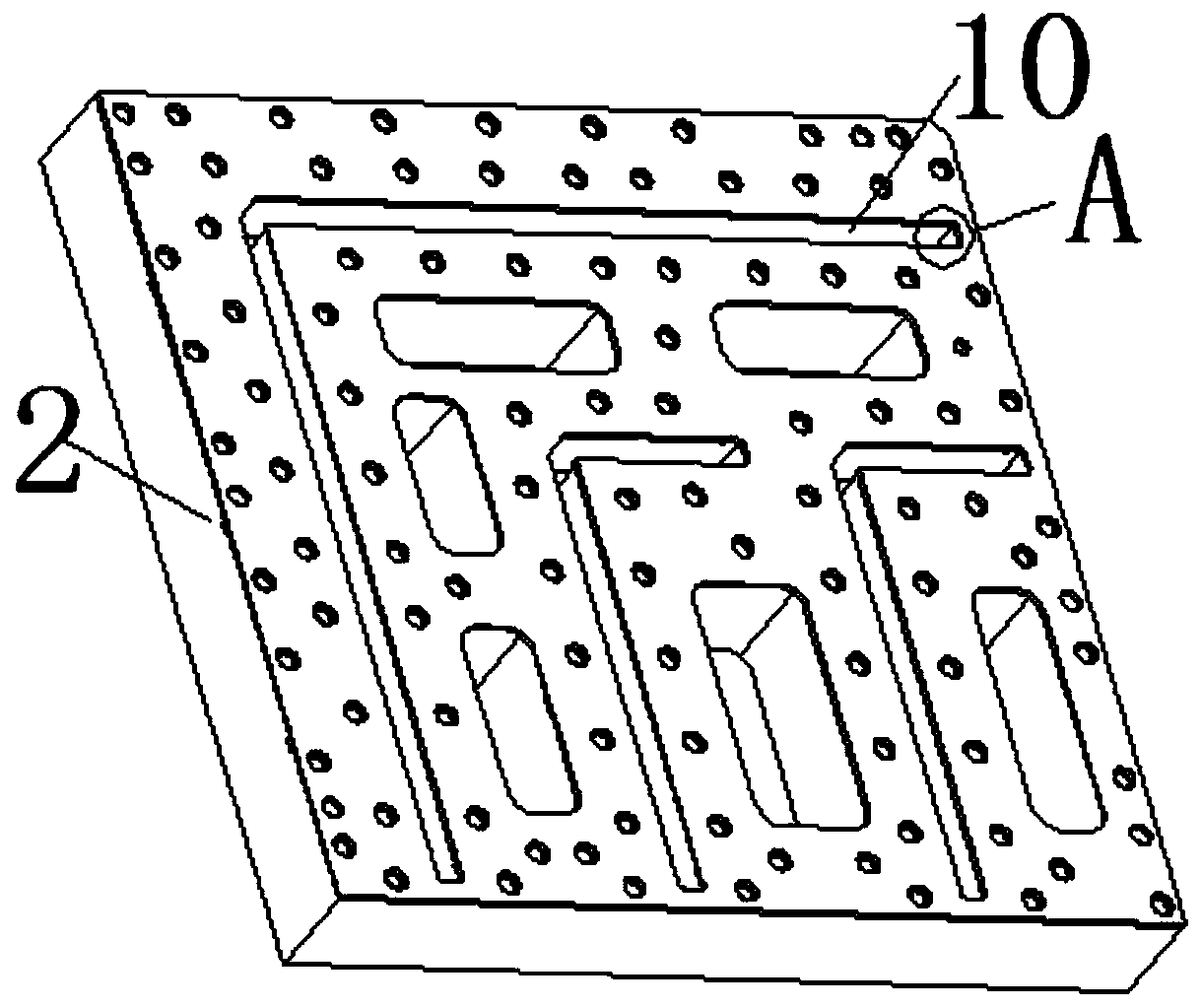
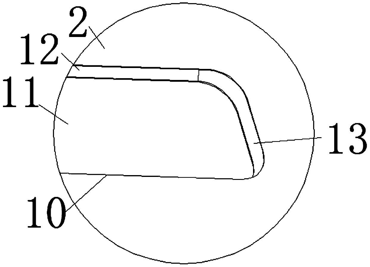
[0003] This application is improved under the existing technology. In the existing technology, when the welding piece is flush with the welding cavity, the welding liquid at the welding seam of the product is not full, and the thin-walled waveguide welding seam is accompanied by virtual welding and light leakage. The welding rate is poor, easy to crack, affecting the signal quality, and failing to meet the product requirements; when the distance between the solder piece and the welding cavity is 1.0mm, there are redundant things such as flowing marks and granular protrusions around the product weld, due to the self-generated waveguide Structural reasons, the excess is difficult to remove, which has a serious impact on the later surface treatment and signal quality

Method used


Image

  • Soldering lug allowance supporting device for quick processing and welding of curved waveguide
  • Soldering lug allowance supporting device for quick processing and welding of curved waveguide
  • Soldering lug allowance supporting device for quick processing and welding of curved waveguide

Examples


Embodiment Construction

[0020] The following will clearly and completely describe the technical solutions in the embodiments of the present invention with reference to the accompanying drawings in the embodiments of the present invention. Obviously, the described embodiments are only some, not all, embodiments of the present invention. Based on the embodiments of the present invention, all other embodiments obtained by persons of ordinary skill in the art without making creative efforts belong to the protection scope of the present invention.

[0021] In the description of the present invention, it should be noted that the terms "center", "upper", "lower", "left", "right", "vertical", "horizontal", "inner", "outer" etc. The indicated orientation or positional relationship is based on the orientation or positional relationship shown in the drawings, and is only for the convenience of describing the present invention and simplifying the description, rather than indicating or implying that the referred d...


PUM

PropertyMeasurementUnit
thicknessaaaaaaaaaa

Abstract

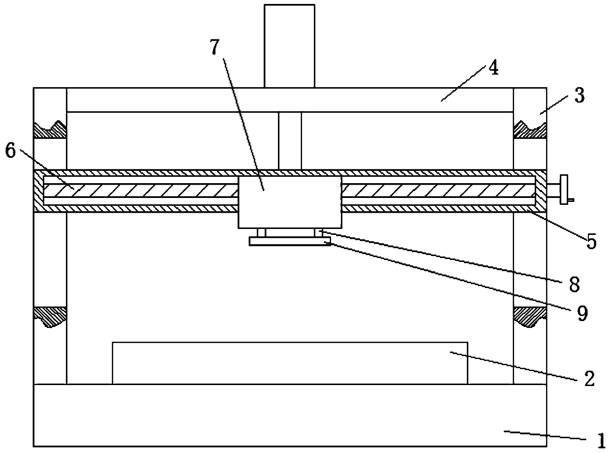
The invention discloses a soldering lug allowance supporting device for quick processing and welding of a curved waveguide. The soldering lug allowance supporting device comprises a base, a processingplate is fixedly mounted at the top of the base, a plurality of sets of welding cavities are formed in the processing plate, a soldering lug body is arranged in each welding cavity, the outer wall ofeach soldering lug body is in abutted connection with a first limiting sheet and a second limiting sheet, each first limiting sheet is in a long-strip shape, and each second limiting sheet is in C-shaped; and the inner wall of each welding cavity is in abutted connection with the side, away from the corresponding soldering lug body, of the corresponding first limiting sheet, the inner wall of each welding cavity is in abutted connection with the side, away from the corresponding soldering lug body, of the corresponding second limiting sheet, as the thickness of each first limiting sheet and each second limiting sheet is 0.5 mm, the spacing between each soldering lug body and the inner wall of the corresponding welding cavity is 0.5 mm, and meanwhile, the most appropriate retention schemeappears. According to the soldering lug allowance supporting device, welding fluid at the seam of a product welded by the scheme is full, the welding penetration rate reaches 90%, fault welding or welding lacking do not exist, flowing and printing stains around the seam do not exist, the welding effect is high, the quality is high, and post processing saves time and labor force.

Description

technical field [0001] The invention relates to the field of curved waveguides, in particular to an auxiliary device for soldering sheet allowance for rapid processing of curved waveguide welding. Background technique [0002] The waveguide elbow is also called a curved waveguide, and its longitudinal axis direction is a section of waveguide that changes suddenly. The function of the curved waveguide is to change the direction of energy transmission. The requirements for the curved waveguide are: small reflection (that is, small mismatch) and no reduction in breakdown power. There are two types of curved waveguides: one is the front curved waveguide, and the other is the H-surface curved waveguide. The waveguide characteristic impedance of the curved part will change, and the smaller the radius of curvature, the greater the change. Due to the popularization of combined waveguide components, the processing efficiency, cost and quality of waveguides are particularly importa...

Claims


Application Information

Patent Timeline
Patent Type & Authority Applications(China)
IPC IPC(8): B23K37/04
CPCB23K37/0435
Inventor 石勇
Owner 南京驰韵科技发展有限公司
Learn More