
A device for cleaning inner holes of pipe parts

A technology for pipe parts and cleaning devices, which is applied to cleaning hollow objects, cleaning methods and utensils, chemical instruments and methods, etc., can solve the problems of insufficient cleaning of the inner wall in the horizontal direction, and achieve high efficiency, simple operation, and sufficient cleaning Effect

Active Publication Date: 2021-06-22
浙江合奥机械科技有限公司
View PDF7 Cites 0 Cited by
  • Summary
  • Abstract
  • Description
  • Claims
  • Application Information

AI Technical Summary

Problems solved by technology

[0005] The object of the present invention is to solve the shortcomings of the prior art by clamping vertically and washing from the upper end of the pipe parts, and the cleaning brush rotates to clean and retracts downwards to solve the problem that the cleaning method of the pipe parts is horizontal. Cleaning, making the technical problem of insufficient cleaning of the horizontal cleaning inner wall

Method used


Image

  • A device for cleaning inner holes of pipe parts
  • A device for cleaning inner holes of pipe parts
  • A device for cleaning inner holes of pipe parts

Examples


Embodiment 1

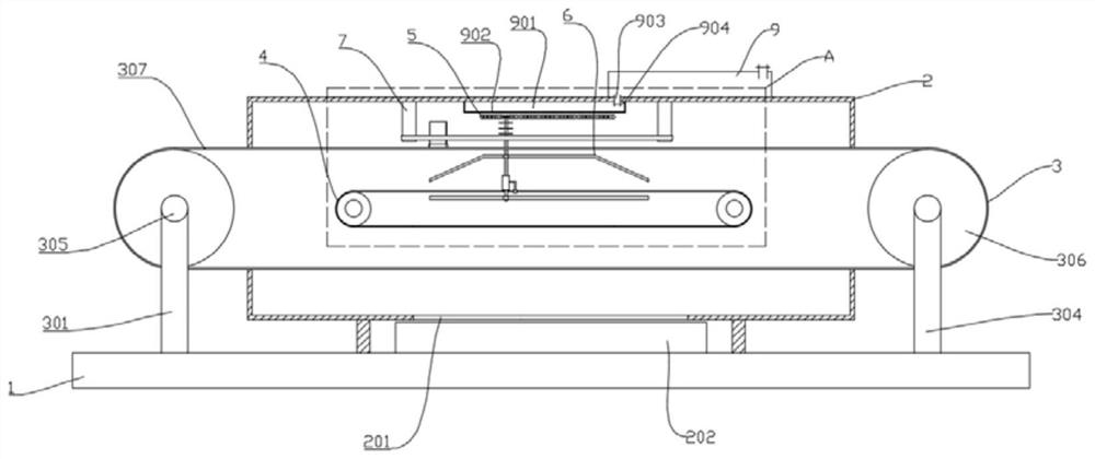
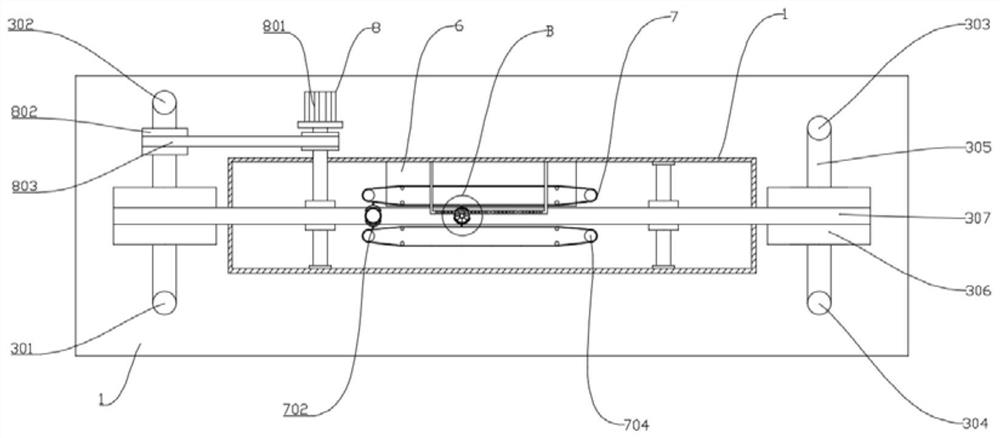
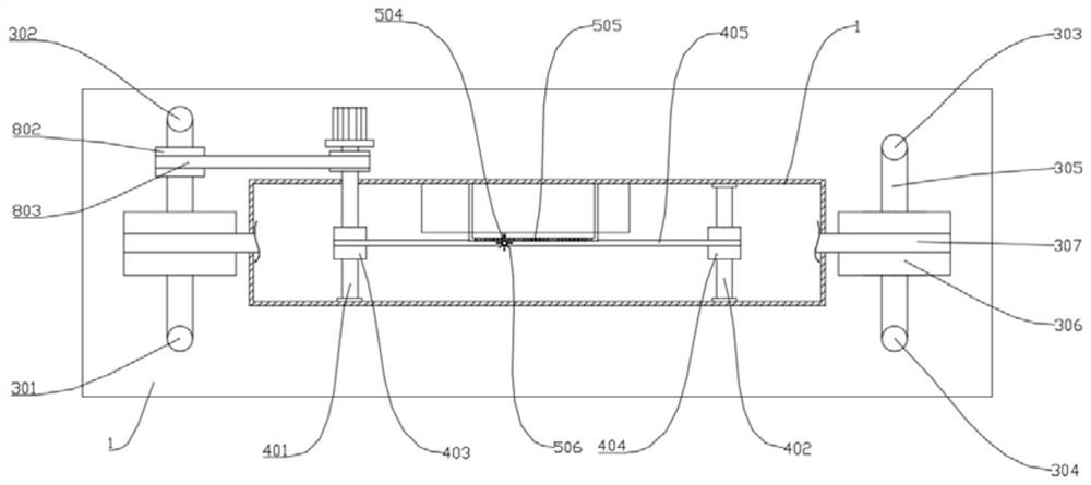
[0035] Such as Figure 1 to Figure 7 As shown, the present invention provides a cleaning device for inner holes of pipe parts, which includes a bottom plate 1 and a box body 2, the box body 2 is centrally installed on the bottom plate 1; a transmission group 3 is installed at both ends of the bottom plate 1 ; No. 2 transmission group 4, cleaning group 5, guide group 6 and clamping group 7 are installed inside the box body 2, and a power group 8 is arranged on the rear side of the box body 2; the No. 1 transmission group 3 runs through the box body left and right 2. No. 2 transfer group 4 is located inside No. 1 transfer group 3. Cleaning group 5 is installed on the upper end of No. 2 transfer group 4 and passes through the upper end of No. 1 transfer group 3. Cooperate, the clamping group 7 is installed on the upper end of the No. 1 transmission group 3 and cooperates with the cleaning group 5, the power group 8 cooperates with the No. 1 transmission group 3 and the No. 2 tran...

Embodiment 2

[0047] Such as Figure 1 to Figure 7 As shown, the components that are the same as or corresponding to those in the first embodiment are marked with the corresponding reference numerals in the first embodiment. For the sake of simplicity, only the differences from the first embodiment will be described below. The difference between this embodiment two and embodiment one is: as Figure 7 As shown, the left and right ends of the No. 1 conveyor belt 307 are provided with support columns a10, and the left and right ends of the chain 404 are provided with support columns b11; ;

[0048] Working process: install the part 12 on the ring chuck 701, start the motor 801, and make the first transmission group 3 and the second transmission group 4 drive, the part 12 moves on the first conveyor belt 307, when the part 12 moves to the clamping At one end of group 7, the arc claw 702 at the tip of the No. 3 conveyor belt 703 covers the part 12 and moves with the part 12. When the arc claw ...


PUM


Abstract

The invention relates to the technical field of inner hole cleaning devices, in particular to an inner hole cleaning device for pipe parts, which is provided with a clamping group, and after the parts are installed on the ring chuck, the parts are driven to move by the No. When holding the inside of the group, relying on the movement of the parts to drive the arc jaws of the clamping group to move, so that the arc clamps clamp the parts along the shape of the No. 3 conveyor belt to realize the automatic grasping function; a cleaning group is provided, and the cleaning group is equipped with gears The brush rod moves up and down along the shape of the guide group, so that the pinion on the brush rod meshes with the gear bar. With the movement of the brush rod driven by the second transmission group, the brush rod rotates. Under the action of the guide group, it moves vertically; installing the parts vertically can better clean the inner wall of the parts and make the cleaning more sufficient.

Description

technical field [0001] The invention relates to the technical field of inner hole cleaning devices, in particular to an inner hole cleaning device for pipe parts. Background technique [0002] When the pipe parts are reproduced and used, some stains, oil and impurities are easy to stick to the inner wall. The inner wall of the pipe parts is not easy to clean, so that the inner wall is damaged to a certain extent, and problems such as rust occur, which will also affect the use of the pipe parts. Pipe parts cooperate with the service life of equipment. [0003] The authorized announcement number is CN201920170818.6, which is a Chinese invention patent, which discloses a steel pipe cleaning equipment. The invention relates to surface treatment equipment, specifically a steel pipe cleaning equipment; including a frame, a transmission device, a clamping device and Cleaning device. The cleaning device includes a fixed frame, a cleaning shaft and a water inlet pipe. The fixed fram...

Claims


Application Information

Patent Timeline
Patent Type & Authority Patents(China)
IPC IPC(8): B08B9/027
CPCB08B9/027
Inventor 赵见平
Owner 浙江合奥机械科技有限公司
Learn More