Drying device for machine part production

A technology for drying devices and mechanical accessories, applied in drying, drying machine, drying gas arrangement, etc., can solve the problems of poor air flow effect of sheet metal parts, long drying time, and affecting the production efficiency of accessories, etc., to achieve Improve the effect of heat transfer, increase the effect of deformation, and maintain the effect of ventilation

Active Publication Date: 2020-03-31
ZHUZHOU HUAXIN PRECISION IND
View PDF6 Cites 4 Cited by
  • Summary
  • Abstract
  • Description
  • Claims
  • Application Information

AI Technical Summary

Problems solved by technology

[0004] Based on the technical problem that the air flow effect of the sheet metal parts located in the middle is poor when the existing drying device is used, resulting in long drying time and affecting the production efficiency of accessories, the present invention proposes a drying device for mechanical parts production

Method used


Image

  • Drying device for machine part production
  • Drying device for machine part production
  • Drying device for machine part production

Examples


Embodiment 1

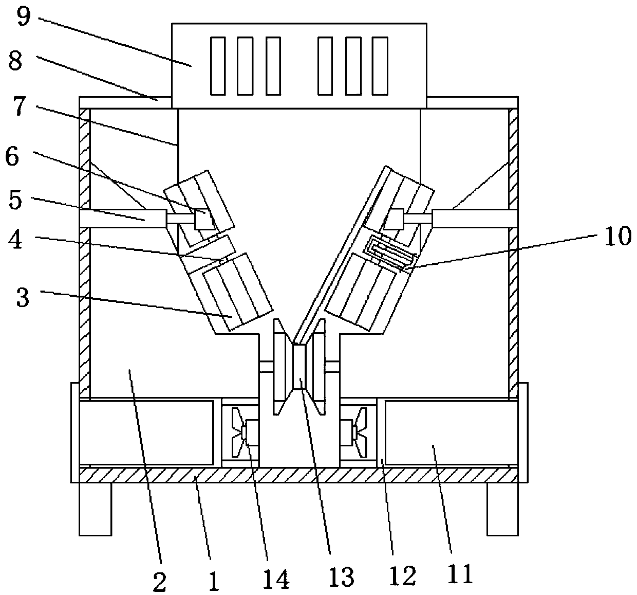
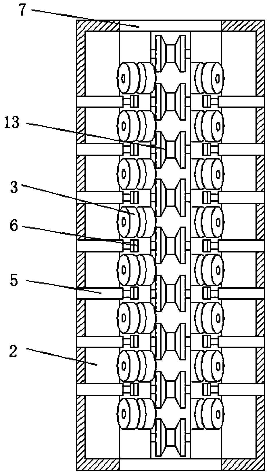
[0029] refer to Figure 1-4 , a drying device for the production of mechanical parts, comprising a box body 1, the top of the box body 1 is fixedly installed with a box cover 8, and the two ends of the box body 1 are respectively provided with material openings 7, and both inner sides of the box body 1 are fixed. A support frame 2 is installed, and a plurality of exhaust passages 12 are formed between the support frame 2 and the bottom inner wall of the box body 1, a conveying wheel 13 is installed between the two support frames 2 through bearings, and the two support frames 2 are mutually A plurality of connecting frames 10 are fixedly installed on the adjacent side, the end of the connecting frame 10 is installed with a rotating shaft 4 through a bearing, and both ends of the rotating shaft 4 are fixedly installed with a wiping mechanism 3, and the inner part of the supporting frame 2 is fixedly installed There is a driving mechanism, and the driving mechanism is connected w...

Embodiment 2

[0036] refer to Figure 1-3 and Figure 5 , a drying device for the production of mechanical parts, the wiping mechanism 3 includes a secondary connecting column 36 and a plurality of sponge wheels 34 sleeved on the outside of the secondary connecting column 36, and there are two adjacent sponge wheels 34. gap.

[0037] The wiping mechanism 3 further includes a fleece wheel 35 sleeved on the outer side of the auxiliary connecting column 36 , and the fleece wheel 35 and the sponge wheel disc 34 are staggered.

[0038] In this embodiment, the wiping mechanism 3 is constituted by staggered velvet wheels 35 and sponge wheels 34 that are sleeved on the outside of the auxiliary connecting column 36. When the wiping mechanism 3 transports the sheet metal parts, the velvet wheel 35 and the sponge wheel 34 The gap between them ensures the effect of hot air circulation, and the outer surface of the flannel wheel 35 can effectively wipe the surface of the sheet metal parts, so as to av...


PUM


Abstract

The invention belongs to the technical field of machine part production, in particular to a drying device for machine part production. In view of the problems that when an existing drying device is used, a sheet metal part located in the middle is poor in air flowing effects, the drying time is caused to be long, and the part production efficiency is influenced, the following scheme is put forward: the device comprises a box body, a box cover is fixedly mounted at the top end of the box body, material openings are formed in the two ends of the box body respectively, supporting frames are fixedly mounted on the two sides of the interior of the box body, and a plurality of exhaust channels are formed between the supporting frames and the inner wall of the bottom of the box body. In the forward moving process, hot air blown to the surface of a sheet metal part is used for effectively drying the sheet metal part; and meanwhile, when a wiping mechanism conveys the sheet metal part, water spots on the surface of the sheet metal part can be wiped and absorbed, the drying efficiency of a solution on the surface of the sheet metal part is improved, the sheet metal part obliquely moves, thetwo sides of the sheet metal part can be heated and dried by hot air, and the drying efficiency of the sheet metal part is further improved.

Description

technical field [0001] The invention relates to the technical field of production of mechanical parts, in particular to a drying device for the production of mechanical parts. Background technique [0002] Machinery refers to the general term for machines and institutions, and is a tool device that can help people reduce the difficulty of work or save labor, while complex machinery is composed of two or more simple machines. Any modern industry and engineering fields need to apply machinery, that is In people's daily life, more and more machines are used, such as automobiles, bicycles, clocks, cameras, washing machines, refrigerators, air conditioners, vacuum cleaners and so on. [0003] The washing machine is a cleaning appliance that uses electrical energy to produce mechanical action to wash clothes. It is a commonly used living machine in home life. The back panel of the washing machine is an important sheet metal accessory. In the production process of the back panel sh...

Claims


Application Information

Patent Timeline
Patent Type & Authority Applications(China)
IPC IPC(8): F26B15/12F26B5/14F26B21/00F26B3/04
CPCF26B3/04F26B5/14F26B15/122F26B21/004
Inventor 李辉
Owner ZHUZHOU HUAXIN PRECISION IND
Why Eureka
Try Eureka