
Heat storage device adopting concentric compounding a phase change material and water

A technology of phase change material and heat storage device, applied in the field of heating equipment, can solve the problem of slow heat storage speed of a heat storage box, and achieve the effect of fast heat storage

Pending Publication Date: 2020-03-31
北方瑞能(内蒙古)集团有限公司
View PDF0 Cites 4 Cited by
  • Summary
  • Abstract
  • Description
  • Claims
  • Application Information

AI Technical Summary

Problems solved by technology

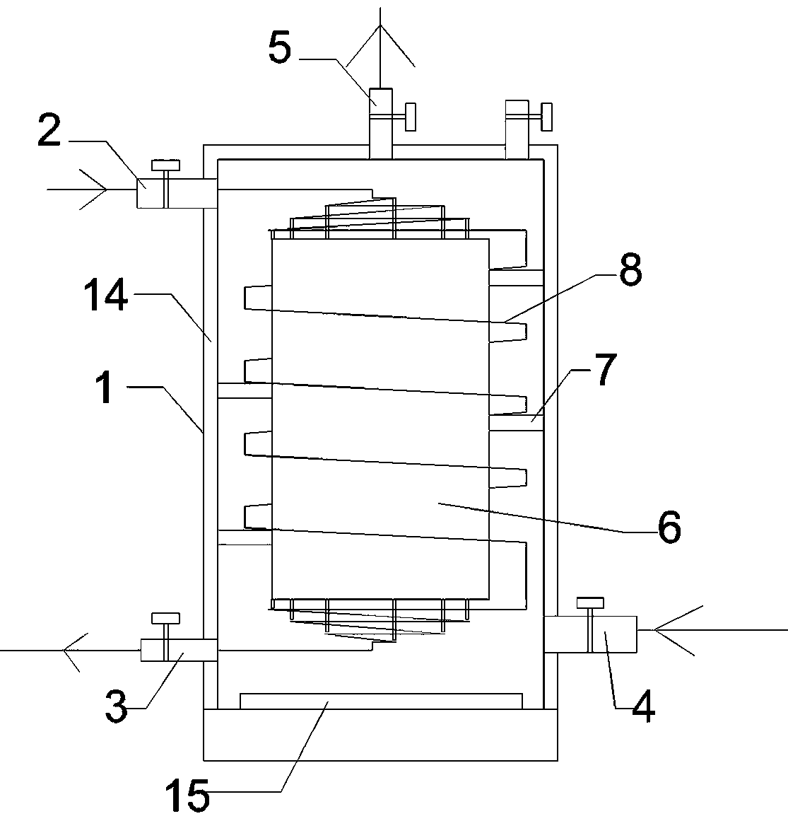
[0002] Phase change thermal storage heating is the storage or release of heat by utilizing the characteristics of materials that can absorb or release a large amount of latent heat when the phase state changes from solid-liquid or liquid-gas. Compared with the traditional variable temperature heat storage process, the phase change process The temperature of the medium material remains almost constant. In the heating project, when the energy is sufficient, the medium and low temperature phase change material can be used to store the heat in the hot water in the phase change material, and the phase change of the phase change material can be used to release heat when the energy is scarce. For heat supply, it is currently widely used in valley electricity storage and heating, that is, the valley electricity is stored in phase change materials at night and used in the heat storage heating process of heating during the day; the heat storage box is a phase change heat storage heating The core component in the system, however, the existing heat storage tank generally has the problem of slow heat storage speed, so this application designs a heat storage device using phase change materials and water concentric composite

Method used


Image

  • Heat storage device adopting concentric compounding a phase change material and water
  • Heat storage device adopting concentric compounding a phase change material and water
  • Heat storage device adopting concentric compounding a phase change material and water

Examples


Embodiment Construction

[0020] In order to enable those skilled in the art to better understand the technical solution of the present invention, the present invention will be further described in detail below in conjunction with the accompanying drawings. The following description is only used to illustrate the technical solution of the present invention and not limit it.

[0021] In describing the present invention, it should be understood that the terms "center", "longitudinal", "transverse", "upper", "lower", "front", "rear", "left", "right", " The orientations or positional relationships indicated by "vertical", "horizontal", "top", "bottom", "inner" and "outer" are based on the orientations or positional relationships shown in the drawings, and are only for the convenience of describing the present invention and Simplify the description, rather than indicate or imply that the device or element referred to must have a specific orientation, be constructed and operate in a specific orientation, and ...


PUM


Abstract

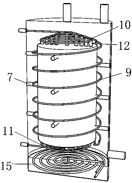
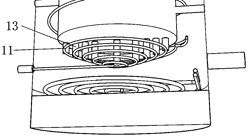
The invention discloses a heat storage device adopting concentric compounding a phase change material and water. The heat storage device comprises a cylindrical shell body; for the shell body, a hot water inlet pipe is arranged at the upper left part, a hot water return pipe is arranged at the lower left part, a cold water inlet pipe is arranged at the lower right part, and a hot water outlet pipeis arranged in the center of the top surface; a cylindrical metal cylinder is concentrically installed in the center in the shell body; a phase change heat storage material is packaged in the metal cylinder; the outer side wall of the metal cylinder is fixedly connected with the inner side wall of the shell body through a metal fixed rod, so that the metal cylinder can be concentrically installedin the center in the shell body; a space outsides the metal cylinder is filled with the water; a heat exchange pipe is installed on the outer side of the metal cylinder in a surrounding manner; and awater inlet at the upper end of the heat exchange pipe communicates with the hot water inlet pipe, and a water outlet at the lower end communicates with the hot water return pipe. Compared with an existing heat storage device, the heat storage device is capable of performing heat storage at a faster speed.

Description

technical field [0001] The invention relates to a heat storage device, in particular to a heat storage device using phase-change materials and water concentrically compounded; it belongs to the technical field of heating equipment. Background technique [0002] Phase change thermal storage heating is the storage or release of heat by utilizing the characteristics of materials that can absorb or release a large amount of latent heat when the phase state changes from solid-liquid or liquid-gas. Compared with the traditional variable temperature heat storage process, the phase change process The temperature of the medium material remains almost constant. In the heating project, when the energy is sufficient, the medium and low temperature phase change material can be used to store the heat in the hot water in the phase change material, and the phase change of the phase change material can be used to release heat when the energy is scarce. For heat supply, it is currently widely...

Claims


Application Information

Patent Timeline
Patent Type & Authority Applications(China)
IPC IPC(8): F24D13/04F24D15/02F24D19/10F28D20/02
CPCF24D13/04F24D15/02F24D19/1096F28D20/021F24D2200/08Y02E60/14
Inventor 李成成李成员崔涛王红广王永强张腾张飞王国伟
Owner 北方瑞能(内蒙古)集团有限公司
Learn More