
High-speed and low-speed cooperative operation biological centrifugal equipment based on acceleration control

A kind of centrifugal equipment, high and low speed technology, applied in centrifuges and other directions, can solve the problems of long time, destroy red blood cells, hemolysis, etc., to achieve high efficiency, improve mixing speed, and complete separation.

Inactive Publication Date: 2020-03-31
陈强
View PDF8 Cites 2 Cited by
  • Summary
  • Abstract
  • Description
  • Claims
  • Application Information

AI Technical Summary

Problems solved by technology

[0004] The main purpose of the present invention is to overcome the deficiencies of the prior art and provide a biological centrifugal device based on speed-up control with high and low speeds to solve the problem of adding anticoagulant after blood collection and turning it upside down dozens of times to prevent blood coagulation as soon as possible. Centrifugal operation, continuous high-speed centrifugal blood separation will destroy red blood cells and cause hemolysis. Generally, low-speed centrifugation is used for blood separation, and the centrifugation process takes a long time.

Method used


Image

  • High-speed and low-speed cooperative operation biological centrifugal equipment based on acceleration control
  • High-speed and low-speed cooperative operation biological centrifugal equipment based on acceleration control
  • High-speed and low-speed cooperative operation biological centrifugal equipment based on acceleration control

Examples


Embodiment Construction

[0027] The following will clearly and completely describe the technical solutions in the embodiments of the present invention with reference to the accompanying drawings in the embodiments of the present invention. Obviously, the described embodiments are only some, not all, embodiments of the present invention. Based on the embodiments of the present invention, all other embodiments obtained by persons of ordinary skill in the art without making creative efforts belong to the protection scope of the present invention.

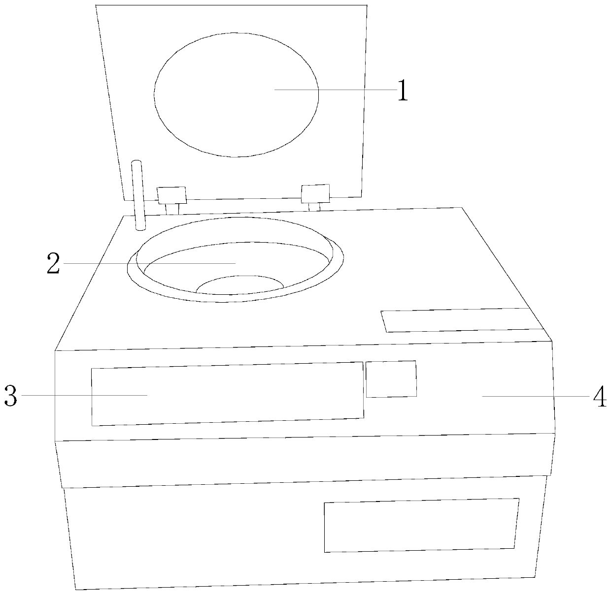
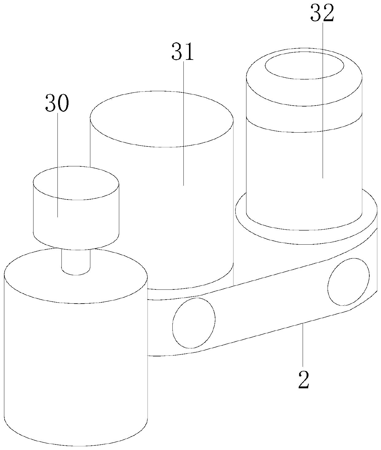
[0028] see Figure 1-9, the present invention provides a technical scheme of biological centrifuge equipment based on speed-up control and high-low speed cooperating operation: its structure includes a cover 1, a separation device 2, a control panel 3, and a centrifuge frame 4. The cover 1 and the centrifuge frame 4-axis connection, the separation device 2 is embedded on the frame 4, the control board 3 is installed on the centrifuge frame 4, the separation de...


PUM


Abstract

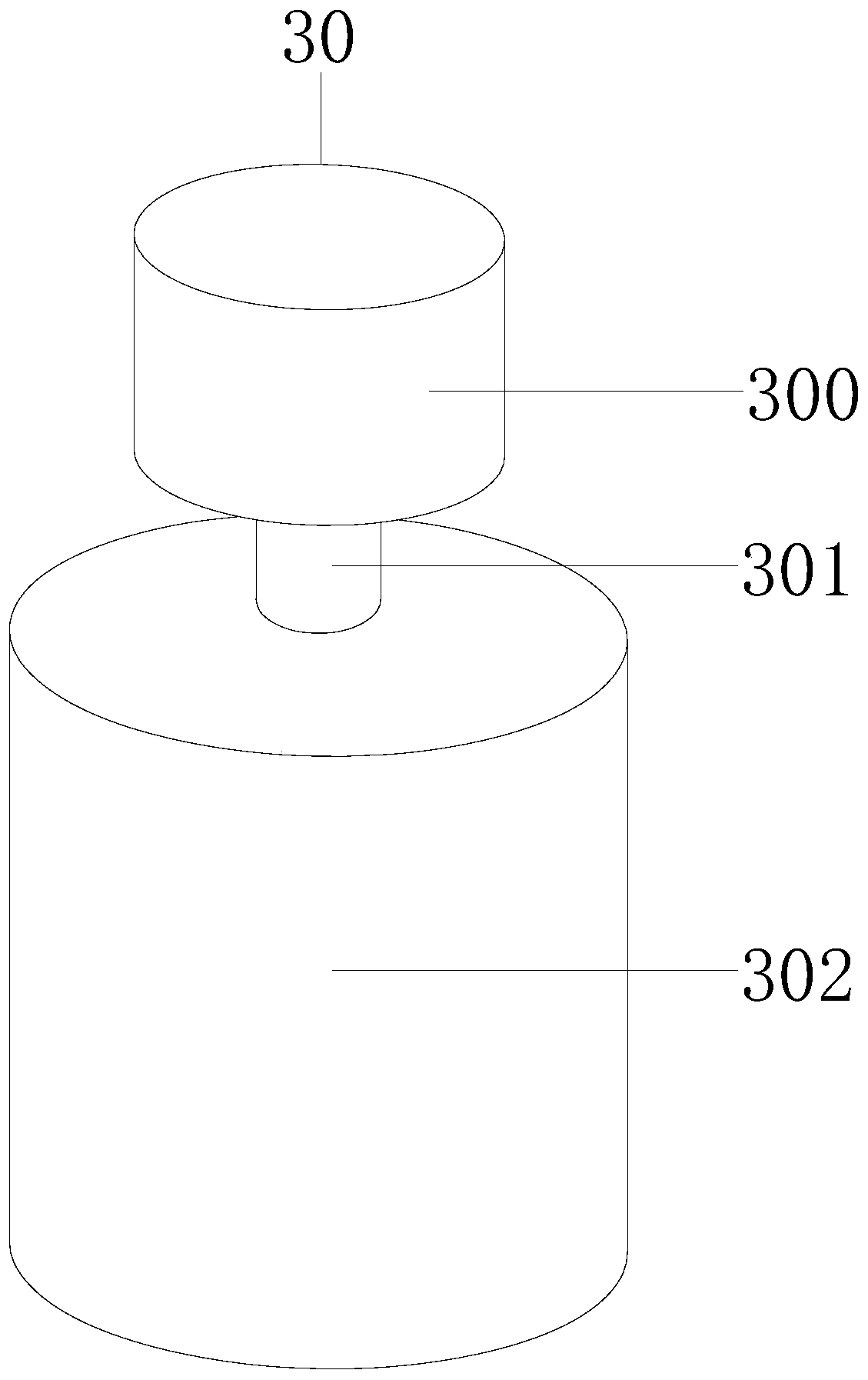
The invention discloses high-speed and low-speed cooperative operation biological centrifugal equipment based on acceleration control. The biological centrifugal equipment structurally comprises a machine cover, a separation device, a control plate and a centrifuge machine frame, wherein the machine cover is connected with the centrifuge machine frame through a shaft, the separation device is embedded on the centrifuge machine frame, the control plate is mounted on the centrifuge machine frame, and the separation device is composed of a low-speed variable-frequency motor, a separation materialbin and an integral motor. According to the high-speed and low-speed cooperative operation biological centrifugal equipment based on the acceleration control, the step of manual addition of an anticoagulant back and forth dozens of times around is replaced through operation of a micro-motor; the operation of a low-speed motor avoids the situation that continuous high-speed centrifugal blood separation is carried out, then red blood cells are damaged, and hemolysis is caused; a high-speed motor performs high-speed rotation separation on delaminated molecules, and further separation is realized; and the blood separation is controlled at different speeds per hour, the mixing speed of blood and the anticoagulant is improved, the stability and the quality of low-speed centrifugal separation ofthe blood are also guaranteed, meanwhile, further high-speed separation is achieved, and the advantages of being thorough in separation and high in efficiency are achieved.

Description

technical field [0001] The invention relates to the field of biological centrifugation, in particular to a biological centrifugation device based on speed-up control with high and low speed coordinated operation. Background technique [0002] Biomolecules refer to all kinds of molecules unique to organisms. Biomolecules have their own unique structures, large molecular weights, many types, large quantities, ever-changing arrangements, and complex structures; different biomolecules have different volumes and densities Generally, centrifugation is used to separate biomolecules, and different centrifugal forces can achieve sedimentation and separation of biomolecules with different densities; using centrifugal equipment to separate different components in blood is called centrifugal blood collection. [0003] In the prior art, it is necessary to add anticoagulant after blood collection and turn it upside down dozens of times to prevent blood coagulation, and then perform centri...

Claims


Application Information

Patent Timeline
IPC IPC(8): B04B9/10B04B9/08B04B9/04B04B5/04B04B7/00
CPCB04B5/0407B04B7/00B04B9/04B04B9/08B04B9/10
Inventor 陈强
Owner 陈强
Learn More