Laser scanning device and scanning method

A laser scanning device and sub-scanning technology, applied in the field of laser scanning, can solve the problems of small scanning field of view, high cost, and large number of parts, and achieve the effect of increasing the vertical scanning field of view and increasing the number

Inactive Publication Date: 2020-03-27
ORADAR TECH CO LTD
View PDF8 Cites 2 Cited by
  • Summary
  • Abstract
  • Description
  • Claims
  • Application Information

AI Technical Summary

Problems solved by technology

In the existing mechanical scanning laser radar, each laser emitting unit can only obtain one scanning line, that is to say, in order to obtain multiple scanning lines, it is necessary to set up multiple laser emitting units and their corresponding laser receiving units, thus As a result, the number of components required inside the equipment is relatively large, which is inconvenient to compress the volume and the cost is high; range and even 360-degree scanning

Method used


Image

  • Laser scanning device and scanning method
  • Laser scanning device and scanning method
  • Laser scanning device and scanning method

Examples


Embodiment Construction

[0032] In order to make the technical problems, technical solutions and beneficial effects to be solved by the embodiments of the present invention clearer, the present invention will be further described in detail below in conjunction with the accompanying drawings and embodiments. It should be understood that the specific embodiments described here are only used to explain the present invention, not to limit the present invention.

[0033] It should be noted that when an element is referred to as being “fixed” or “disposed on” another element, it may be directly on the other element or be indirectly on the other element. When an element is referred to as being "connected to" another element, it can be directly connected to the other element or indirectly connected to the other element. In addition, the connection can be used for both fixing and circuit communication.

[0034] It is to be understood that the terms "length", "width", "top", "bottom", "front", "rear", "left", ...


PUM


Abstract

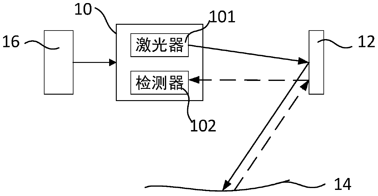
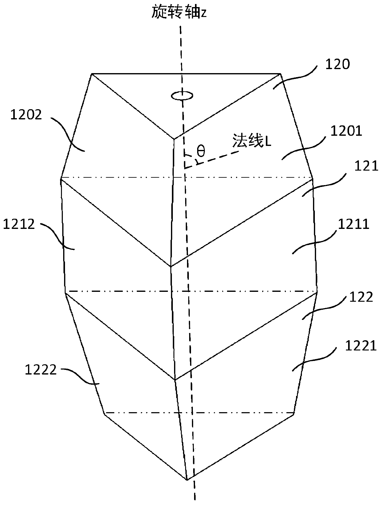
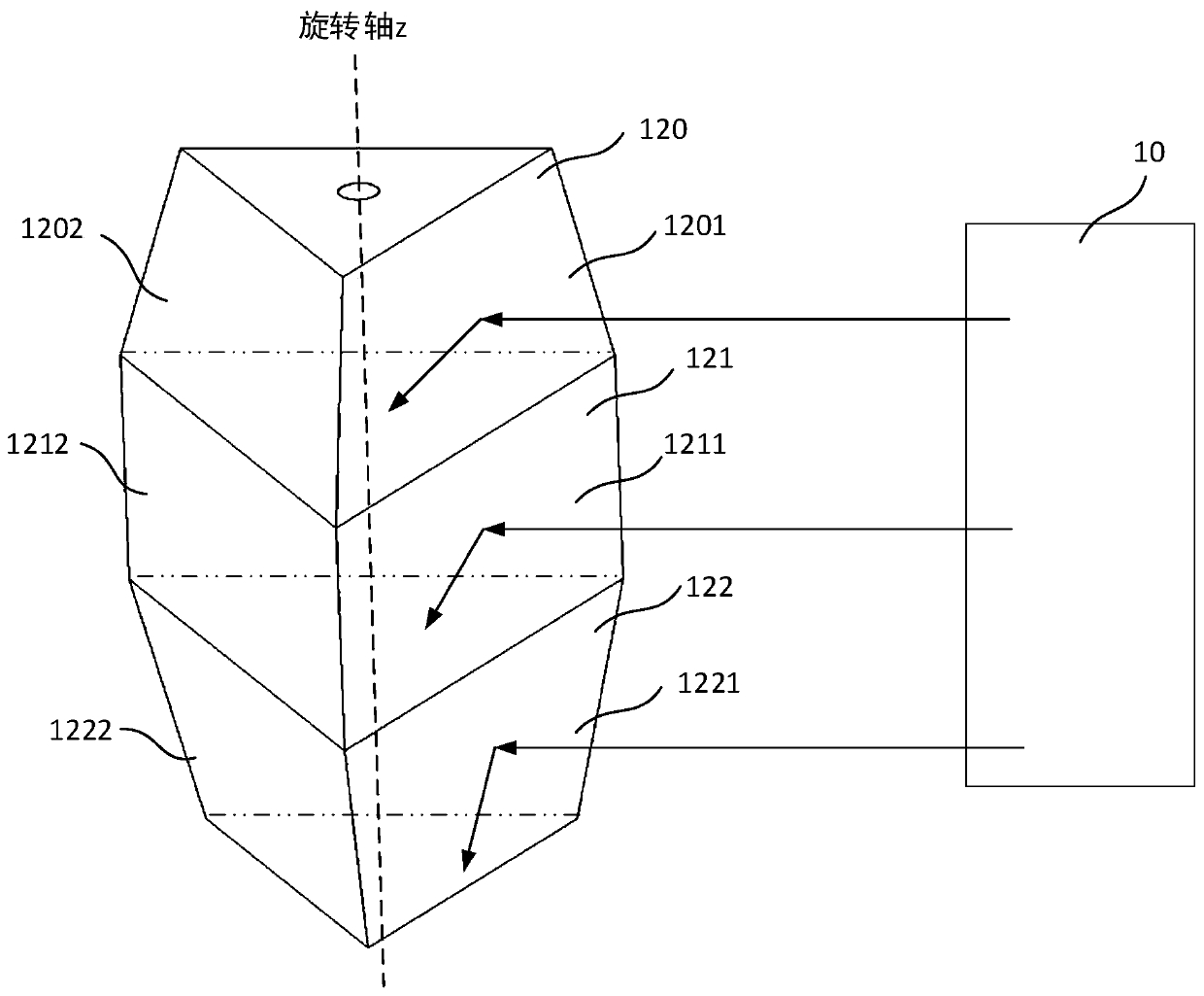
The invention discloses a laser scanning device which comprises a laser array and a detector array which are respectively used for emitting laser beams to a target object and receiving the laser beamsreflected by the target object; the multi-layer scanning prism comprises a plurality of sub-scanning prisms, each sub-scanning prism comprises a plurality of scanning mirror surfaces, and the plurality of scanning mirror surfaces rotate around the same rotating shaft; wherein the normal of each scanning mirror surface and the rotating shaft form a space angle, and the angles of the formed space angles are not completely the same; and the control and processing circuit is used for controlling the laser array to emit a plurality of laser beams and controlling and driving the multi-layer scanning prism to rotate uninterruptedly so as to realize scanning of a target object. The vertical scanning view field angle of the scanning device can be effectively increased, the number of central scanning view field scanning lines can be effectively increased, and specific requirements of different application scenes are met.

Description

technical field [0001] The invention relates to the technical field of laser scanning, in particular to a laser scanning device and a scanning method. Background technique [0002] Lidar is a radar system that emits laser beams to detect the position, speed and other characteristics of the target. It has the advantages of high accuracy, fast operation speed and high efficiency. It is widely used in automotive automatic driving, robot positioning and navigation, space environment mapping, security Security and other fields. [0003] At present, the laser radar system mainly transmits the laser signal to the target object through the internal laser transmitting unit, and receives the echo signal reflected from the target object through the internal laser receiving unit, and records the laser signal from emission to reception. The time difference and the depth information of the target object are calculated, and the intensity information of the target is obtained from the echo...

Claims


Application Information

Patent Timeline
Patent Type & Authority Applications(China)
IPC IPC(8): G01S7/481G01S17/06G01S17/08G01S17/58
CPCG01S7/4817G01S7/4815G01S7/4816G01S17/06G01S17/08G01S17/58
Inventor 罗佳林刘超董俊发
Owner ORADAR TECH CO LTD
Why Eureka
Try Eureka