Eureka AIR delivers breakthrough ideas for toughest innovation challenges, trusted by R&D personnel around the world.

Automatic centering and pressing device for balancing machine rotor with conical inner hole

A technology of automatic centering and pressing device, which is applied in the direction of static/dynamic balance test, measuring device, machine/structural component test, etc. It can solve the problems of inability to use expansion sleeve or chuck positioning, missing, etc., and achieve guarantee Centering, improving measurement accuracy, fast positioning and clamping effects

Pending Publication Date: 2020-03-27
杭州集智机电股份有限公司 +2
View PDF0 Cites 3 Cited by
  • Summary
  • Abstract
  • Description
  • Claims
  • Application Information

AI Technical Summary

Problems solved by technology

However, for some special disc-shaped workpieces, such as rotor workpieces such as motorcycle magneto, the central reference hole is a tapered hole, and expansion sleeves or chucks cannot be used for positioning. heart compression device

Method used


Image

  • Automatic centering and pressing device for balancing machine rotor with conical inner hole
  • Automatic centering and pressing device for balancing machine rotor with conical inner hole
  • Automatic centering and pressing device for balancing machine rotor with conical inner hole

Examples


Embodiment Construction

[0022] The present invention will be further described below in conjunction with the accompanying drawings and specific implementation.

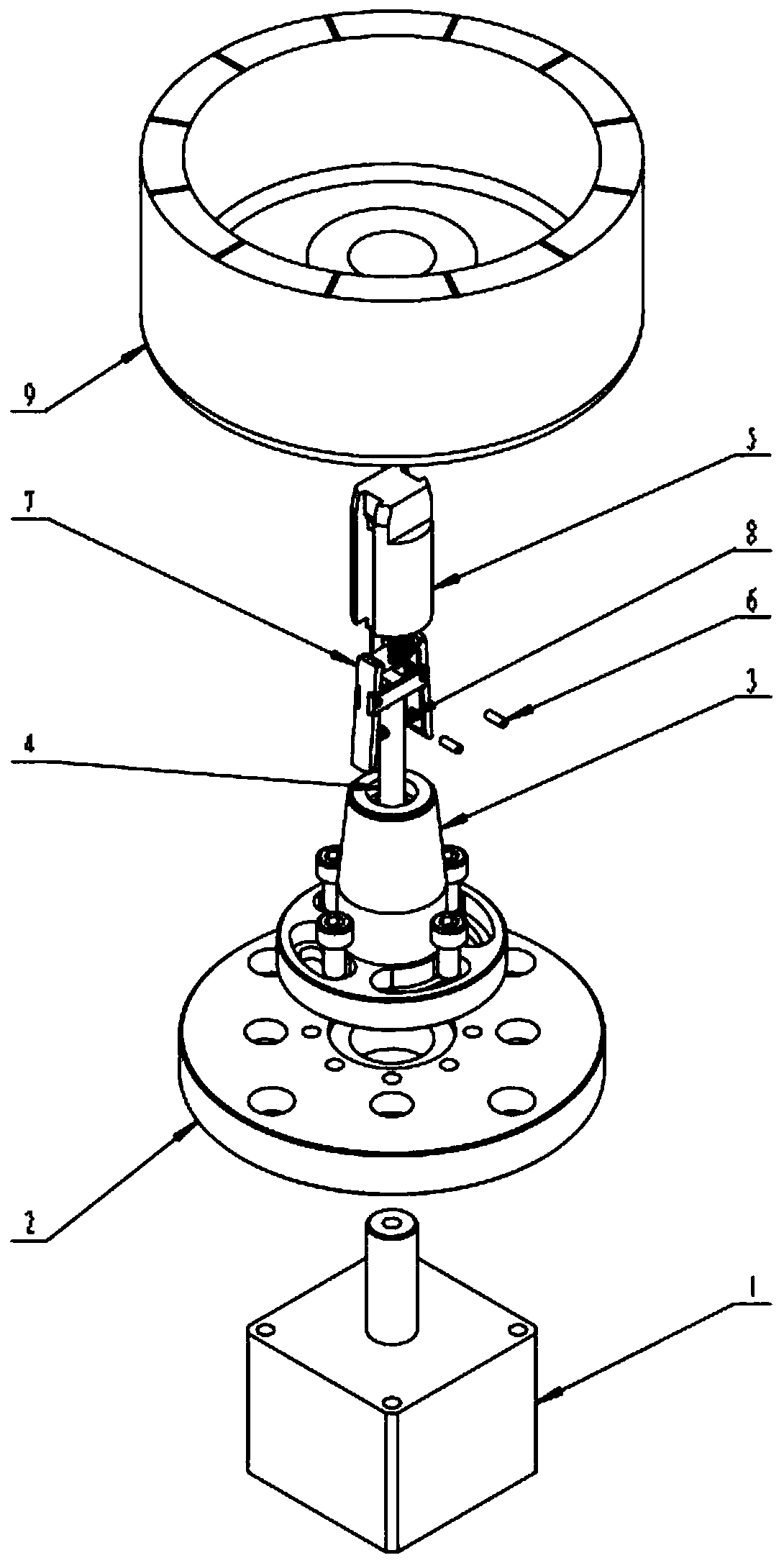
[0023] like figure 1 , Figure 5-Figure 7 As shown, it includes a power element 1, a bottom plate 2, a cone seat 3, a pull rod 4, a guide seat 5, a pressure rod 7 and an elastic element 8; the power element 1 is fixed on the bottom surface of the bottom plate 2, and the bottom of the cone seat 3 is fixed on the top surface of the bottom plate 2. The workpiece 9 is set outside the top of the cone seat 3; the bottom plate 2 and the cone seat 3 are provided with a central through hole and are coaxially connected. The through hole is coaxially fixed with the lower end of the pull rod 4 .

[0024] The guide seat 5 is fixedly installed on the top of the cone seat 3, such as Figure 2-Figure 4 As shown, the guide seat 5 is mainly composed of half cylinders on both sides and a guide block between the two half cylinders, the guide block is fixedly...


PUM


Abstract

The invention discloses an automatic centering and pressing device for a balancing machine rotor with a conical inner hole. The power element is fixed to the bottom face of the bottom plate, the bottom of the cone base is fixed to the top face of the bottom plate, and a workpiece is set outside the top of the cone seat. A power rod of the power element penetrates through the bottom plate and thenis coaxially and fixedly connected with the lower end of the pull rod in the cone base, the guide base is fixedly installed at the top of the cone base and mainly comprises semi-cylinders on the two sides and a guide block, and a hollowed-out cavity is formed below the guide block of the guide base. The size of the two sides of the guide block decreases downward, the pull rod penetrates out of theconical seat and then is coaxially and fixedly connected with the pressing rod in the hollow cavity of the guide seat, the middles of two rotating rods of the pressing rod are hinged, the upper portions of the two rotating rods are connected to the two side faces of the guide block, and the lower portions of the two rotating rods are connected through an elastic element. In the dynamic balance detection process of the rotor with the conical inner hole, rapid positioning and clamping of the rotor are achieved through cooperation of the center positioning component and the pressing positioningcomponent, so that accurate centering is guaranteed, and the system measurement precision is improved.

Description

technical field [0001] The invention relates to an automatic centering and pressing device, in particular to an automatic centering and pressing device for a rotor with a conical inner hole of a balancing machine. Background technique [0002] The market for rotors such as motorcycle magneto is huge and the prospects are bright. In the mass production process, due to the influence of materials and manufacturing processes, there is an initial imbalance. When the rotor with excessive unbalance is rotating at high speed, it will generate vibration, bring noise, shorten the service life, and even bring danger. Therefore, the dynamic balance correction of the rotor must be carried out. [0003] The measurement of unbalance is the premise of dynamic balance correction processing. In order to improve the efficiency, the automatic centering and pressing device is indispensable. For ordinary rotors, expansion sleeves or chucks are generally used to locate the center hole of the wor...

Claims


Application Information

Patent Timeline
IPC IPC(8): G01M1/02G01M1/16
CPCG01M1/02G01M1/16
Inventor 龚向阳李宝娟郭小伟周小燕姚凯强
Owner 杭州集智机电股份有限公司
Why Eureka
Eureka Blog
Learn More