


Quick Research
Generate reliable direction feasibility study reports for your R&D in just a few steps.

Technical Q&A
Discover and master advanced knowledge NOW. Basics, ideas, possibilities, all at once.

Find Solutions
As an expert in R&D theories, this can generate solutions to your technical problems instantly.

Evaluate Feasibility
Analyze your overall solution with one click, know your potential R&D risks in advance.

Monitor Landscape
Get weekly tech updates, stay abreast of the latest tech innovations and key insights.
Riveting method of hollow rivet and oval head screw
A hollow rivet and oblate head technology, applied in the field of mechanical processing, can solve the problems of low work efficiency and high scrap rate, and achieve the effects of high production efficiency, short processing cycle and overcoming technical difficulties.
- Summary
- Abstract
- Description
- Claims
- Application Information
AI Technical Summary
Problems solved by technology
Method used
Image

Examples
specific Embodiment approach 1
[0011] Specific implementation mode one: combine Figure 1 to Figure 8 Explain, the riveting method of a hollow rivet and flat head screw described in this embodiment includes the following steps:
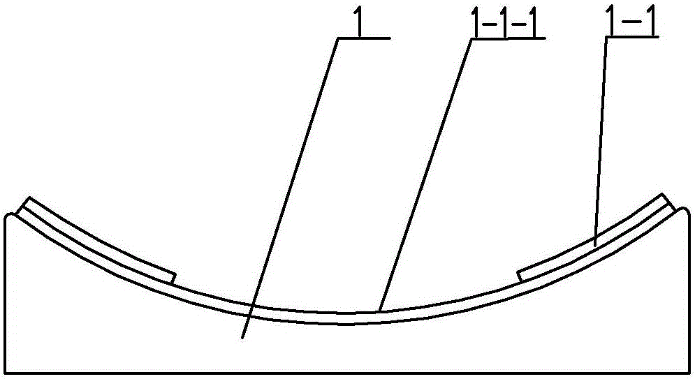
[0012] Step 1: Assembling the hollow rivet 5: First, fix the support seat 1 on the workbench, the lower end surface of the support seat 1 is a plane, the upper end surface of the support seat 1 is an arc surface, and the arc surface of the upper end surface of the support seat 1 is in line with the The arc of the cover plate 4 is the same, install the small end of the hollow rivet 5 vertically upwards into the mounting hole on the cover plate 4, and then place the cover plate 4 after the hollow rivet 5 is assembled on the upper end surface of the support seat 1 ;
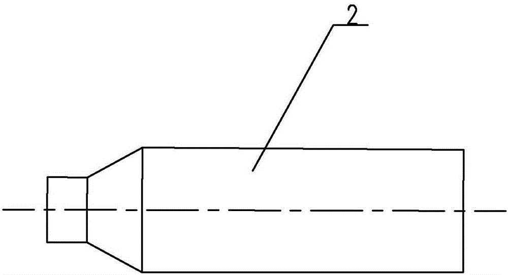
[0013] Step 2: Flange: Flange pin 2 is a stepped shaft, and the position between the shafts of flange pin 2 is provided with a conical surface. The diameter of the small end of flange pin 2 is smaller than the inner dia...
specific Embodiment approach 2
[0017] Specific implementation mode two: combination Figure 1 to Figure 8 To illustrate, in step 1 and step 3 of this embodiment, a rubber pad 1-1 is laid on the upper surface of the support base 1, and a groove 1-1-1 is provided in the middle of the rubber pad 1-1. Other method steps are the same as those in the first embodiment.
[0018] The rubber pad 1-1 acts as a buffer to prevent the surface of the cover plate 4 and the flat head screw 5 from being bumped during riveting, and the nut of the flat head screw 5 is placed in the groove 1-1-1 to prevent the flat The round head screw 5 interferes with the rubber pad 1-1, which is inconvenient for positioning.
specific Embodiment approach 3
[0019] Specific implementation mode three: combination Figure 1 to Figure 8 It should be noted that in step 1 and step 3 of the present embodiment, the thickness of the rubber pad 1-1 is 1mm-3mm, and the depth of the groove 1-1-1 is 0.5mm-1.5mm. Other method steps are the same as in the second embodiment.
PUM
| Property | Measurement | Unit |
|---|---|---|
| Thickness | aaaaa | aaaaa |
| Depth | aaaaa | aaaaa |
| Thickness | aaaaa | aaaaa |
Abstract
Description
Claims
Application Information
 - R&D Engineer
- R&D Manager
- IP Professional
- Industry Leading Data Capabilities
- Powerful AI technology
- Patent DNA Extraction
Browse by: Latest US Patents, China's latest patents, Technical Efficacy Thesaurus, Application Domain, Technology Topic, Popular Technical Reports.
© 2024 PatSnap. All rights reserved.Legal|Privacy policy|Modern Slavery Act Transparency Statement|Sitemap|About US| Contact US: help@patsnap.com