


Quick Research
Generate reliable direction feasibility study reports for your R&D in just a few steps.

Technical Q&A
Discover and master advanced knowledge NOW. Basics, ideas, possibilities, all at once.

Find Solutions
As an expert in R&D theories, this can generate solutions to your technical problems instantly.

Evaluate Feasibility
Analyze your overall solution with one click, know your potential R&D risks in advance.

Monitor Landscape
Get weekly tech updates, stay abreast of the latest tech innovations and key insights.
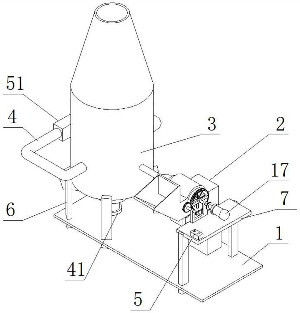
A solid-state slag removal pulverized coal furnace
A slagging coal, solid state technology, applied in solid fuel pretreatment, block/powder supply/distribution, combustion methods, etc. Air entering the furnace, etc.
- Summary
- Abstract
- Description
- Claims
- Application Information
AI Technical Summary
Problems solved by technology
Method used
Image

Examples
Embodiment approach
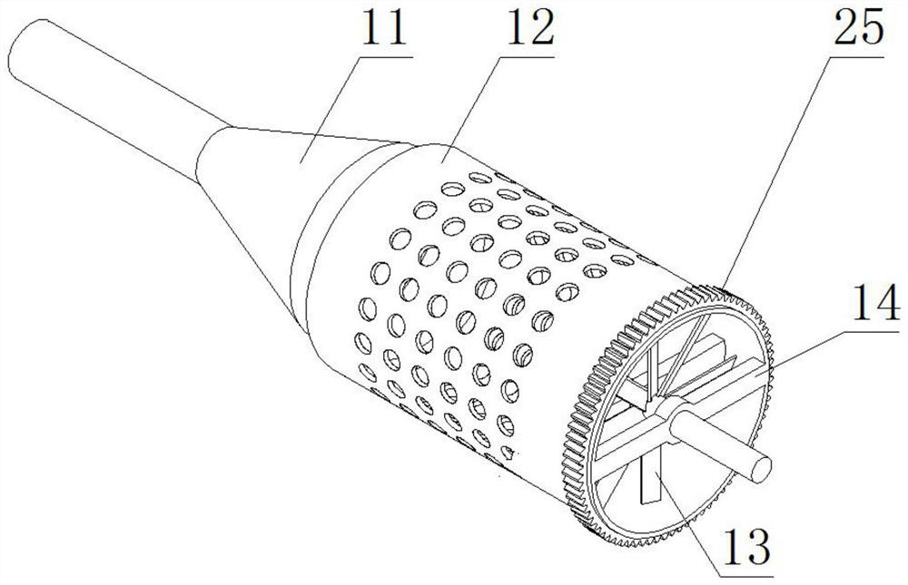
[0033] As a preferred embodiment of the present invention, coal powder holes are provided on the drum punching coal suction device 12 .
[0034] As a preferred embodiment of the present invention, the annular slider 15 and the roller punching coal suction device 12 constitute a sliding pair.
[0035] As a preferred embodiment of the present invention, the wheel shaft 26 is provided with angled blades.
[0036] As a preferred embodiment of the present invention, the elastic plate 35 and the matching hole constitute a sliding pair.
[0037] As a preferred embodiment of the present invention, the other end of the rotary shaft 43 is provided with a turntable 52, and the gap between the turntable 52 and the discharge cover 46 is 0-1 cm.
[0038] As a preferred embodiment of the present invention, a discharge pipe 53 is provided on one side of the discharge cover 46, a slag discharge tank 54 is provided on the bottom frame 1, and the slag discharge pipe 32 and the slag discharge ta...
PUM
 Abstract
Description
Claims
Application Information
 - R&D Engineer
- R&D Manager
- IP Professional
- Industry Leading Data Capabilities
- Powerful AI technology
- Patent DNA Extraction
Browse by: Latest US Patents, China's latest patents, Technical Efficacy Thesaurus, Application Domain, Technology Topic, Popular Technical Reports.
© 2024 PatSnap. All rights reserved.Legal|Privacy policy|Modern Slavery Act Transparency Statement|Sitemap|About US| Contact US: help@patsnap.com