Cold smoke recirculating unit heat conduction oil recovery bypass smoke heat system and control method

A heat system and recycling technology, applied in preheating, feed water heaters, climate sustainability, etc., can solve the problems of affecting fuel burn, unreasonable recovery, complex automatic control operation, etc., to reduce the design pressure level, Reduced initial investment and good thermal stability

Active Publication Date: 2020-03-27
CHINA ENERGY ENG GRP GUANGDONG ELECTRIC POWER DESIGN INST CO LTD
View PDF11 Cites 0 Cited by
  • Summary
  • Abstract
  • Description
  • Claims
  • Application Information

AI Technical Summary

Problems solved by technology

According to the second law of thermodynamics, heat changes from high-grade sensible heat of furnace flue gas to high-grade sensible heat of feed water and low-grade sensible heat of condensate water, and there is a certain irreversible loss of energy work ability, and the overall utilization efficiency of flue gas sensible heat limited
Therefore, it is unreasonable to use the existing air preheater bypass flue system to recover the excess flue gas heat of the cold smoke recirculation unit
[0008] (2) The flue gas exchanges heat with the low-pressure condensate and high-pressure feedwater in the bypass flue, which is equivalent to the parallel operation of the condensate heat exchanger and the l...

Method used


Image

  • Cold smoke recirculating unit heat conduction oil recovery bypass smoke heat system and control method

Examples


Embodiment Construction

[0047] The following will clearly and completely describe the technical solutions in the embodiments of the present invention with reference to the accompanying drawings in the embodiments of the present invention. Obviously, the described embodiments are only some, not all, embodiments of the present invention. Based on the embodiments of the present invention, all other embodiments obtained by persons of ordinary skill in the art without creative efforts fall within the protection scope of the present invention.

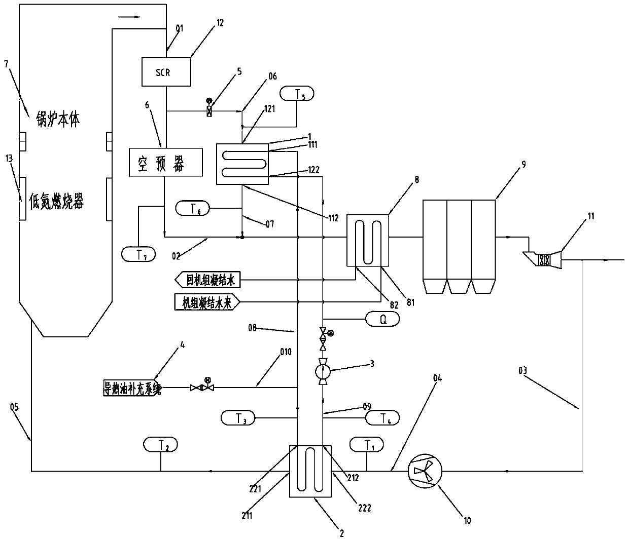
[0048] The following explains the proper nouns that appear in the following technical solutions: cold smoke: refers to the flue gas behind the dust collector or induced draft fan, taking a large coal-fired unit equipped with a low-temperature electrostatic precipitator as an example, the flue gas passes through the dust collector or After the induced draft fan, the dust concentration is less than 100mg / Nm 3 , the temperature is about 70 ~ 150 ℃. Cold smoke recircu...


PUM


Abstract

The invention discloses a cold smoke recirculating unit heat conduction oil recovery bypass smoke heat system. The cold smoke recirculating unit heat conduction oil recovery bypass smoke heat system comprises a bypass smoke cooling device, a recirculating cold smoke heating device, a closed circulating oil pump, a heat conduction oil replenishing system, an adjusting baffle door, an air preheaterand a boiler body. A first inlet of the bypass smoke cooling device communicates with a smoke exhaust port through the adjusting baffle door, and a first outlet of the bypass smoke cooling device communicates with a smoke outlet of the air preheater. The bypass smoke cooling device communicates with the recirculating cold smoke heating device in a circulating manner. The recirculating cold smoke heating device communicates with a cold smoke recirculating draught fan and a hearth dry bottom hopper of the boiler body. The input end of the closed circulating oil pump communicates with a second outlet of the recirculating cold smoke heating device, and the output end of the closed circulating oil pump communicates with a second inlet of the bypass smoke cooling device. The output end of the heat conduction oil replenishing system communicates with an eighth pipeline and is used for replenishing a heat conduction oil circulating medium. A smoke inlet of the air preheater communicates with the smoke exhaust port of the boiler body.

Description

technical field [0001] The invention relates to the field of unit efficiency improvement, in particular to a heat conduction oil recovery bypass flue gas heat system and control method of a cold smoke recirculation unit. Background technique [0002] Flue gas recirculation is a common method used to regulate the outlet steam temperature of the reheater when burning ashless fuel or low ash fuel. At present, the large-scale coal-fired units that use flue gas recirculation to adjust the outlet steam temperature of the reheater are mainly secondary reheat units. The double reheat unit is an advanced coal-fired power generation technology that is internationally mature, efficient, and low-pollution. It has good economic benefits and environmental protection characteristics, and has broad development prospects in my country. [0003] Cold smoke recirculation is to draw part of the cold flue gas (temperature is about 70-150 ℃) from the dust collector or induced draft fan with a re...

Claims


Application Information

Patent Timeline
IPC IPC(8): F23B80/00F23J15/06F23J15/08F22D1/36
CPCF22D1/36F23B80/00F23J15/06F23J15/08Y02E20/30
Inventor 尹进吴阿峰张翔宇刘广林
Owner CHINA ENERGY ENG GRP GUANGDONG ELECTRIC POWER DESIGN INST CO LTD
Why Eureka
Try Eureka