Constant temperature adjusting method for air conditioning type constant temperature hydraulic oil tank

A technology of hydraulic oil tank and constant temperature adjustment, which is applied in the direction of oil supply tank device, fluid pressure actuating device, fixed tubular conduit assembly, etc. The effect of large market and promotion potential, high heat exchange efficiency and compact structure

Inactive Publication Date: 2020-03-27
ZHONGYUAN ENGINEERING COLLEGE
View PDF6 Cites 4 Cited by
  • Summary
  • Abstract
  • Description
  • Claims
  • Application Information

AI Technical Summary

Problems solved by technology

This control method can quickly reach the ideal temperature, but the constant temperature method is more complicated and expensive to use. Because it uses a cooling tower, it occupies a relatively large area, requires a large amount of cooling water, and is inconvenient to move.

Method used


Image

  • Constant temperature adjusting method for air conditioning type constant temperature hydraulic oil tank
  • Constant temperature adjusting method for air conditioning type constant temperature hydraulic oil tank
  • Constant temperature adjusting method for air conditioning type constant temperature hydraulic oil tank

Examples


Embodiment 2

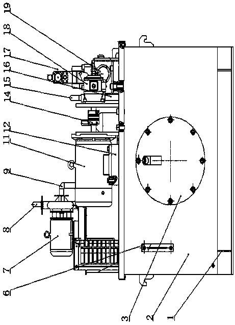
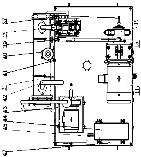
[0030] Example 2, such as Figure 5 As shown, a constant temperature adjustment method of an air-conditioned constant-temperature hydraulic oil tank, the steps are as follows: S1: The evaporator coil of the air-conditioning system of the air-conditioned constant-temperature hydraulic oil tank is connected to the water tank, and the air-conditioning system is based on the oil temperature in the oil tank and the water temperature in the water tank. Perform cooling or heating, and control the temperature of the cooling water in the water tank;

[0031] S2: The water tank is connected to the heat transfer pipe in the heat exchanger through the water inlet pipe, the oil tank is connected to the inner chamber of the heat exchanger through the oil inlet pipe, and the hydraulic oil in the oil tank exchanges heat with the cooling water in the heat exchanger;

[0032] S3: The hydraulic oil that has completed the heat exchange returns to the oil tank through the oil return pipe, and the ...


PUM


Abstract

The invention discloses a constant temperature adjusting method for an air conditioning type constant temperature hydraulic oil tank. According to the constant temperature adjusting method for the airconditioning type constant temperature hydraulic oil tank, an evaporator coil pipe of an air conditioning system is connected into a water tank; the temperature of the cooling water in the water is controlled through heating or refrigerating; the cooling water is introduced into a red copper pipe of a heat exchanger to perform heat exchange with high-temperature hydraulic oil in a heat exchanger,so that precise control of oil temperature is realized. The air conditioning system and the water tank of the air conditioning type constant temperature hydraulic oil tank are arranged at the upper part of an oil tank, and the heat exchanger is arranged on the side surface of the oil tank, so that the space position is greatly reduced. The refrigerating efficiency of the air conditioning type constant temperature hydraulic oil tank is much higher than that of the existing conventional hydraulic station; the hydraulic oil temperature is controlled between 32 and 34 DEG C, so that the power performance of the hydraulic oil is improved; the hydraulic oil is prevented from being emulsified at high temperature; the service life of the hydraulic oil is prolonged; the using amount of the hydraulic oil is reduced; the heat exchange efficiency is high; the hydraulic oil in the oil tank is ensured to be in a constant temperature state; and therefore, the constant temperature adjusting method for the air conditioning type constant temperature hydraulic oil tank has great advantages.

Description

technical field [0001] The invention relates to the technical field of hydraulic oil tanks, in particular to a constant temperature adjustment method for an air-conditioned constant temperature hydraulic oil tank. Background technique [0002] The hydraulic oil in the hydraulic station acts as a transmission medium between energies. At the same time, the viscosity of the hydraulic oil affects the action of the hydraulic device. The viscosity of the hydraulic oil will be affected by the oil temperature. The stability of the oil temperature has a great influence on the normal operation of the hydraulic oil. In order to make the hydraulic station work smoothly, controlling the oil temperature will be a key issue. [0003] In the past, most of the constant temperature fuel tanks were cooled by cooling towers, or by air cooling and heated by heaters. This method can indeed achieve constant temperature control, but it has its own limitations. That is, although the heater can achi...

Claims


Application Information

Patent Timeline
Patent Type & Authority Applications(China)
IPC IPC(8): F15B21/0423F15B21/0427F15B1/26F25D17/02F25D16/00F28D7/16F28F21/08F28F9/24
CPCF15B1/26F25D16/00F25D17/02F28D7/16F28F9/24F28F21/085F15B21/0423F15B21/0427
Inventor 安向东王东豪刘雪霞
Owner ZHONGYUAN ENGINEERING COLLEGE
Why Eureka
Try Eureka