
Engine cooling fan control system

A technology for engine cooling and fan control, which is applied in the direction of engine cooling, coolant flow control, engine components, etc. It can solve the problems of slow response, slow speed, and slow flow of silicone oil fans, etc., to achieve lower water temperature, quick response, The effect of increasing the speed

Inactive Publication Date: 2020-03-27
DONGFENG COMML VEHICLE CO LTD
View PDF9 Cites 6 Cited by
  • Summary
  • Abstract
  • Description
  • Claims
  • Application Information

AI Technical Summary

Problems solved by technology

[0005] The method of controlling the speed of the silicone oil fan in this patent is controlled by the engine. When the engine works at low speed and heavy load for a long time, the low speed of the engine at this time causes the silicone oil to flow slowly, which makes the response of the silicone oil fan slow and the speed increases. slow

Method used


Image

  • Engine cooling fan control system

Examples


Embodiment 1

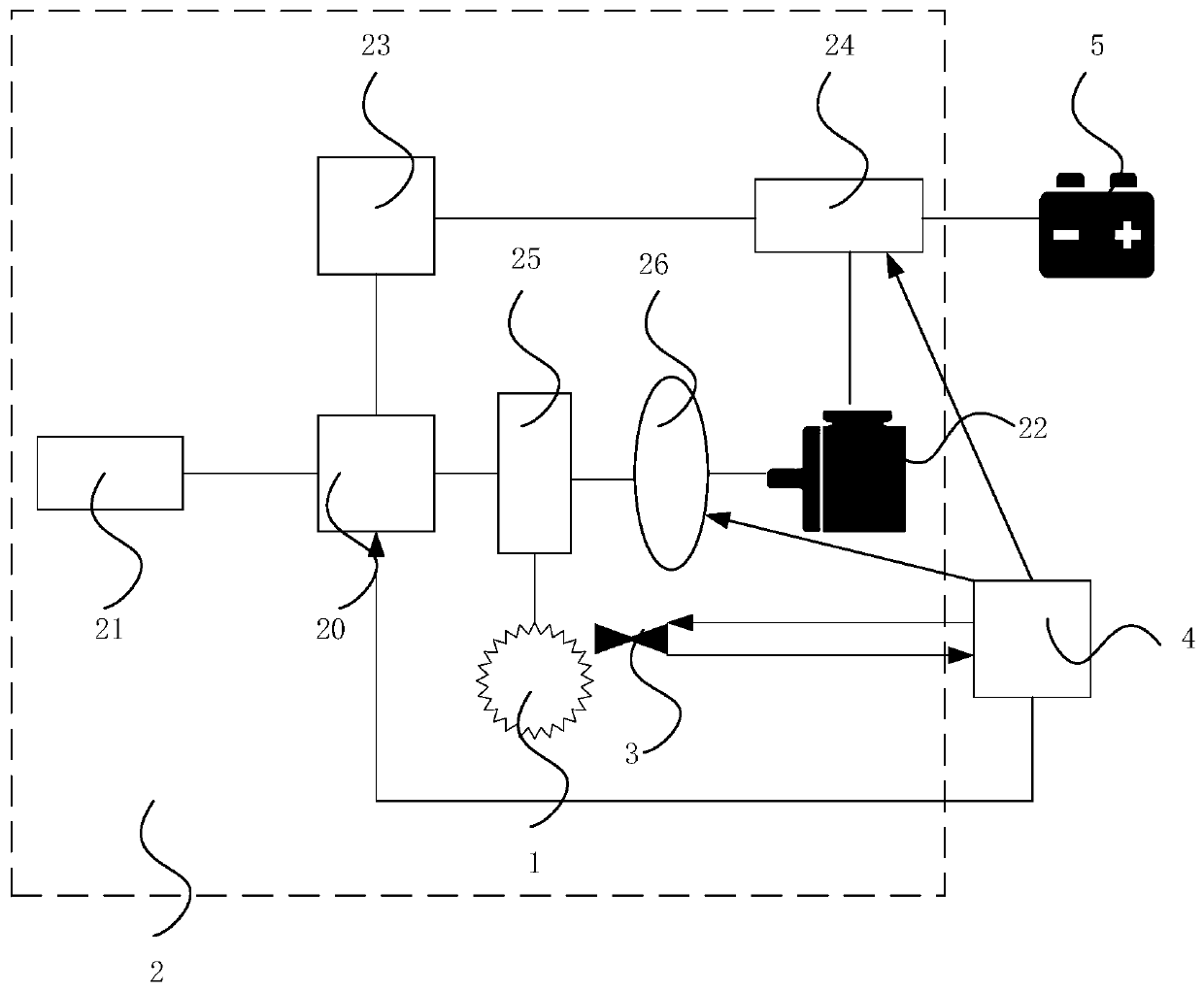
[0031] see figure 1 As shown, the embodiment of the present invention provides an engine cooling fan control system, which includes a silicon oil fan 1, a power system 2, a fan sensor 3 and a controller 4; The controller 4 is newly added, and the electronic control unit ECU has been connected with the engine 21, so the arrangement and connection of lines are reduced. The threshold value of the speed of the silicone oil fan 1 is calibrated in advance. When the engine water temperature is 90°C, the speed of the silicone oil fan 1 is set as the threshold value, so that the engine water temperature is kept at 90°C, preventing the engine from being too low and insufficient in power, and too high from affecting engine performance. The power system 2 includes a power splitter 20, an engine 21 and an electric motor 22 connected to the power splitter 20. In the embodiment of the present invention, by adding the electric motor 22, the water temperature of the engine can be satisfied whe...

Embodiment 2

[0035] The basic content of embodiment 2 of the present invention is the same as embodiment 1, and difference is:

[0036]The power system 2 of Embodiment 2 of the present invention further includes a generator 23 , which is connected to the power splitter 20 and the motor 22 , and is used to convert the power of the engine 21 into electric power and distribute it to the motor 22 . When the speed of the silicone oil fan 1 is lower than the threshold, the controller 4 distributes the power of the engine 21 to the generator 23 by controlling the power splitter 20, and the generator 23 converts the power into electricity, and transmits the electricity to the motor 22, and the motor 22 Electricity is converted into power to drive the silicon oil fan 1 to rotate rapidly.

Embodiment 3

[0038] The basic content of embodiment 3 of the present invention is the same as embodiment 2, and difference is:

[0039] The control system also includes a storage battery 5, which is connected to the generator 23. When the speed of the silicon oil fan 1 is lower than the threshold, the controller 4 distributes the power of the engine 21 to the generator 23 by controlling the power splitter 20. 23 converts the power into electricity, and transmits part of the electricity to the motor 22. The motor 22 converts the electricity into power to drive the silicon oil fan 1 to rotate quickly, and the remaining part is transmitted to the battery 5 to charge the battery 5. The battery 5 is used for During the operation of the vehicle, it supplies power to the electrical components of the vehicle.


PUM


Abstract

The invention discloses an engine cooling fan control system. The control system involves a silicone oil fan, a power system, a fan sensor and a controller; the power system involves a power distributor, an engine and a motor, wherein the engine and the motor are connected with the power distributor; the fan sensor is used for detecting the rotation speed of the silicone oil fan; and the controller is connected with the power system and the fan sensor, and meanwhile, the controller is used for distributing power of the engine to the motor by controlling the power distributor when the rotationspeed of the silicone oil fan is lower than a threshold value, driving the silicone oil fan through the motor so as to improve the rotation speed of the silicone oil fan, and controlling the engine todrive the silicone oil fan to speed down by controlling the power distributor when the rotation speed of the silicone oil fan is higher than the threshold value. The engine cooling fan control systemcan improve the rotation speed of the silicone oil fan and improve the response speed of the silicone oil fan through the motor under the condition that the rotation speed of the silicone oil fan islower than the threshold value.

Description

technical field [0001] The invention relates to the technical field of heat dissipation control, in particular to an engine cooling fan control system. Background technique [0002] During the driving process of the car, as the operating environment and working conditions change, the water temperature of the engine is also constantly changing. In order to ensure normal driving, it is necessary to adjust the water temperature of the engine in real time. For example, in hot summer, when the engine works at low speed and heavy load for a long time, the water temperature of the engine is high. At this time, we should actively reduce its temperature; When the water temperature of the engine is low, we should increase its temperature at this time. [0003] At present, in commercial vehicles, silicon oil fans are mainly used to cool down the engine water temperature. Silicon oil fans use silicone oil as a medium to transmit torque and then drive the fan to rotate. The existing ele...

Claims


Application Information

Patent Timeline
Patent Type & Authority Applications(China)
IPC IPC(8): F01P7/04F04D27/00
CPCF01P7/048F04D27/004
Inventor 许振营姜江汤自丽张少华张磊
Owner DONGFENG COMML VEHICLE CO LTD
Learn More