Pneumatic concrete wet spraying machine

A wet blasting machine and concrete technology, which is used in earth-moving drilling, wellbore lining, tunnel lining, etc., can solve the problems of material jamming, pneumatic device pressure gas pressure reduction, large impact material head, etc., to improve the continuity and stability, Reduce the required space and ensure the effect of the shotcrete effect

Pending Publication Date: 2020-03-27
焦作市倍特矿业设备有限公司
View PDF10 Cites 0 Cited by
  • Summary
  • Abstract
  • Description
  • Claims
  • Application Information

AI Technical Summary

Problems solved by technology

This type of wet spraying machine is prone to the problem of material jam during the spraying process, and due to the insufficient design of the material conveying device, the pressure gas output by the pneumatic device is prone to decrease, which leads to the problem of uneven material spraying
However, the drum blanking method makes the material spray outward in pulse form during the spraying construction, which has poor continuity and stability. At the same time, the pulse spray is easy to form a large impact material head, which is not conducive to construction operations
The material conveying device often needs its own power input, which increases the complexity and space of the equipment, making the equipment relatively stable when working in a small space

Method used


Image

  • Pneumatic concrete wet spraying machine
  • Pneumatic concrete wet spraying machine

Examples


Embodiment

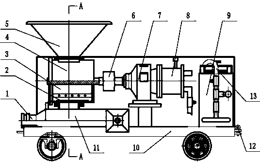
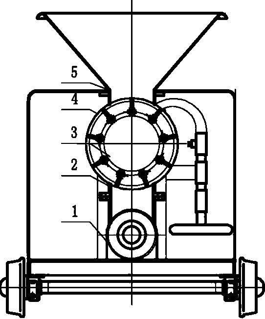
[0017] Such as figure 1 and figure 2 As shown, a pneumatic concrete wet spraying machine includes a chassis 10, a grout mixing and spraying device arranged at the front of the chassis 10, a power unit arranged at the middle of the chassis 10 and an accelerator tank 9 arranged at the rear of the chassis 10, The tail end of the chassis 10 is provided with a connecting pin 12; the mixing and spraying device includes a hopper 5 arranged on the top, a mixing bucket 4 communicated with the bottom of the hopper 5, a rotor 3 arranged in the mixing bucket 4, The sealing plate 2 arranged at the bottom outlet of the mixing tank 4, the material storage chamber 11 communicated with the bottom outlet of the mixing tank 4 and the nozzle 1 arranged at the front end of the material storage room 11; The reducer 7, the pneumatic fan 8 installed on the input shaft side of the reducer 7 and the coupling 6 installed on the output shaft side of the reducer 7, the coupling 6 and the rotor 3 in the ...


PUM


Abstract

The invention discloses a pneumatic concrete wet spraying machine, and the wet spraying machine comprises a chassis, a slurry mixing and spraying device at the front part of the chassis, a power device in the middle of the chassis and an accelerator box at the rear part of the chassis, wherein a connecting bolt is arranged at the tail end of the chassis; the slurry mixing and spraying device comprises a hopper, a material mixing barrel communicated with the bottom of the hopper, a rotor in the material mixing barrel, a sealing plate at an outlet in the bottom of the material mixing barrel, a material storage chamber communicated with an outlet in the bottom of the material mixing barrel and a nozzle at the front end of the material storage chamber. The power device comprises a speed reducer fixed in the middle of the chassis, a pneumatic fan mounted on the input shaft side of the speed reducer and a coupler mounted on the output shaft side of the speed reducer, wherein the coupler is fixedly connected with a rotor shaft in the mixing barrel, and an outlet of the accelerator box is connected with the storage chamber through a hose. According to the invention, an on-site compressed air source is used as power, and the space required by equipment is reduced; a direct slurry mixing and discharging mode is adopted to replace rotary drum discharging and pneumatic conveying slurry spraying to achieve flexible and continuous slurry spraying, the slurry spraying continuity and stability are improved, and the slurry spraying effect is guaranteed.

Description

technical field [0001] The invention relates to the technical field of mining equipment, in particular to a pneumatic concrete wet spraying machine. Background technique [0002] Wet spraying machine is a common spraying equipment in mining equipment. It has the advantages of excellent spraying effect and not easy to appear dust. Generally, the concrete material is transported by pumping, and then the concrete material is sprayed by pneumatic means. workplace. [0003] The working method of the current wet spraying machine is generally to use the screw to transport the material, and then the material is transported to the spraying pipeline by the way of drum feeding, and then the slurry is sprayed to the workplace through the pressure gas. This type of wet spray machine is prone to the problem of material jam during the spraying process, and due to the insufficient design of the material conveying device, the pressure gas output by the pneumatic device is prone to decrease,...

Claims


Application Information

Patent Timeline
IPC IPC(8): E21D11/10
CPCE21D11/105
Inventor 赵长旗
Owner 焦作市倍特矿业设备有限公司
Why Eureka
Try Eureka