Method for electroplating carbon plate grid of lead-carbon battery with thin lead plating layer

A lead-carbon battery and lead coating technology, which is applied to battery electrodes, electrode carriers/collectors, circuits, etc., can solve problems such as poor mechanical properties, decreased electrical properties of lead-carbon batteries, and damage to hard and brittle characteristics

Active Publication Date: 2020-03-27
ZHAOQING LEOCH BATTERY TECH
View PDF6 Cites 2 Cited by
  • Summary
  • Abstract
  • Description
  • Claims
  • Application Information

AI Technical Summary

Problems solved by technology

[0004] For the negative carbon grid of traditional lead-carbon batteries, it is made of various materials such as graphite, silicon, titanium and cellulose after pressing and sintering. The lead paste is built into the negative carbon grid, and its main material is graphite. , compared with traditional lead-acid batteries using lead or lead alloy negative grids, it can indeed reduce the use of heavy metal lead, but the traditional negative carbon grid is obtained by pressing and sintering the main material of graphite, which is greatly affected When impacted by an external force, it is easy to be damaged due to the hard and brittle characteristics, and there is a problem of poor mechanical properties
[0005] Furthermore, the surface of the traditional carbon grid is mainly carbon elements. When the solder paste is filled in the carbon grid, the affinity between the solder paste and the surface of the carbon grid is much lower than that of the solder paste and the lead grid or the lead alloy plate. grid affinity, leading to a decline in the electrical performance of lead-carbon batteries

Method used


Image

  • Method for electroplating carbon plate grid of lead-carbon battery with thin lead plating layer

Examples


Embodiment Construction

[0029] In order to make the above objects, features and advantages of the present invention more comprehensible, specific implementations of the present invention will be described in detail below in conjunction with the accompanying drawings. In the following description, numerous specific details are set forth in order to provide a thorough understanding of the present invention. However, the present invention can be implemented in many other ways different from those described here, and those skilled in the art can make similar improvements without departing from the connotation of the present invention, so the present invention is not limited by the specific implementations disclosed below.

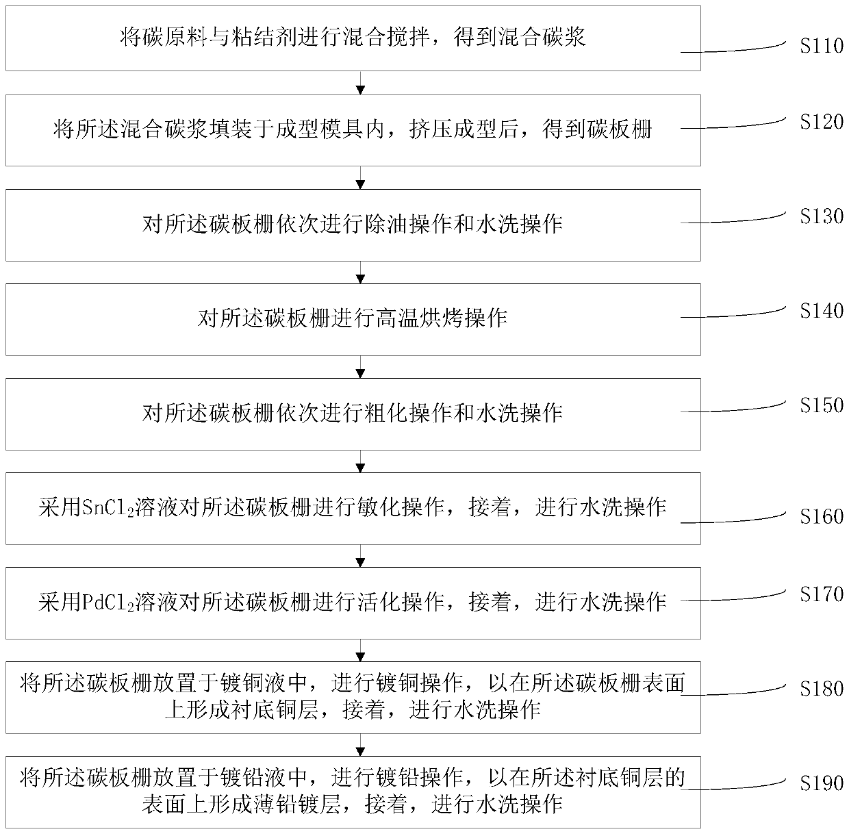
[0030] like figure 1 As shown, an electroplating method for a lead-carbon battery carbon grid thin lead coating of an embodiment includes the following steps:

[0031] S110: mixing and stirring the carbon raw material and the binder to obtain a mixed carbon slurry.

[0032] Through ...


PUM


Abstract

A method for electroplating the carbon plate grid of a lead-carbon battery with a thin lead plating layer includes the following steps: filling a forming mold with a mixed carbon slurry to obtain a carbon plate grid; successively de-oiling the carbon plate grid; baking the carbon plate grid at high temperature; successively roughening the carbon plate grid; using a SnCl2 solution to sensitize thecarbon plate grid; using a PdCl2 solution to activate the carbon plate grid; placing the carbon plate grid in a copper plating solution and performing a copper plating operation to form a substrate copper layer on the surface of the carbon plate grid; placing the carbon plate grid in a lead plating solution and performing a lead plating operation to form a thin lead plating layer on the surface ofthe substrate copper layer. The substrate copper layer not only has a good adhesion ability to the surface of the carbon plate grid, but also has a good binding ability to the electroplated lead layer. The method can form the electroplated lead layer on the surface of the carbon plate grid, thereby enabling the carbon plate grid and solder paste to have high affinity. The copper plating layer andthe lead plating layer coat the carbon plate grid such that the carbon plate grid has better mechanical properties.

Description

technical field [0001] The invention relates to the technical field of lead-carbon batteries, in particular to an electroplating method for a thin lead coating on a carbon grid of a lead-carbon battery. Background technique [0002] At present, the electrodes of lead-acid batteries are mainly made of lead and its oxides, and the electrolyte is a battery of sulfuric acid solution. Since the invention of lead-acid batteries by the Frenchman Plante in 1859, lead-acid batteries have experienced more than 150 years of development. Lead-acid batteries have low cost, long life, good safety performance, and the recycling rate of waste batteries is as high as 95%. Therefore, it has always been the most widely used product in the battery field. [0003] With the rapid development of electric vehicles and electric bicycles, a new battery based on lead-carbon technology has gradually emerged, that is, lead-carbon batteries. This battery adds activated carbon as a buffer material to the...

Claims


Application Information

Patent Timeline
IPC IPC(8): C25D5/54C25D3/38C25D3/34C25D5/10C25D5/16H01M4/84H01M4/66H01M4/68
CPCC25D3/34C25D3/38C25D5/10C25D5/16C25D5/54H01M4/661H01M4/663H01M4/667H01M4/68H01M4/84Y02E60/10
Inventor 邵勤思张树祥傅倩如臧银亮
Owner ZHAOQING LEOCH BATTERY TECH
Why Eureka
Try Eureka