
Nano-copper connecting piece efficient pneumatic stamping device for factory production

A technology of factory production and stamping equipment, which is applied in the field of high-efficiency pneumatic stamping equipment for nano-copper connectors used in factory production. It can solve problems such as easy tilting of the top plate stamping, damage to the cylinder, and high-proportion control of product stability. The effect of uniform pressure and avoiding damage

Inactive Publication Date: 2020-03-27
JIANGYIN SANLING METAL PROD
View PDF8 Cites 4 Cited by
  • Summary
  • Abstract
  • Description
  • Claims
  • Application Information

AI Technical Summary

Problems solved by technology

[0002] Nano-copper is a new type of material made of nano-materials. Its strength is higher than that of ordinary copper, so it is widely used. Nano-copper connectors can connect nano-copper together. Nano-copper connectors are usually produced by stamping devices. Traditional The single-step stamping method not only has low production efficiency, but also cannot control the stability of the product at a high rate. Manual loading and unloading is time-consuming and labor-intensive. The top platen on the stamping device is prone to tilt during stamping, which affects the stamping quality. The generated debris cannot be cleaned in time, and the dust in the air is easily brought into the cylinder when the cylinder is inhaled, which is likely to cause damage to the cylinder and bring certain adverse effects to actual use

Method used


Image

  • Nano-copper connecting piece efficient pneumatic stamping device for factory production
  • Nano-copper connecting piece efficient pneumatic stamping device for factory production
  • Nano-copper connecting piece efficient pneumatic stamping device for factory production

Examples


Embodiment Construction

[0028] The following will clearly and completely describe the technical solutions in the embodiments of the present invention with reference to the accompanying drawings in the embodiments of the present invention. Obviously, the described embodiments are only some, not all, embodiments of the present invention. Based on the embodiments of the present invention, all other embodiments obtained by persons of ordinary skill in the art without making creative efforts belong to the protection scope of the present invention.

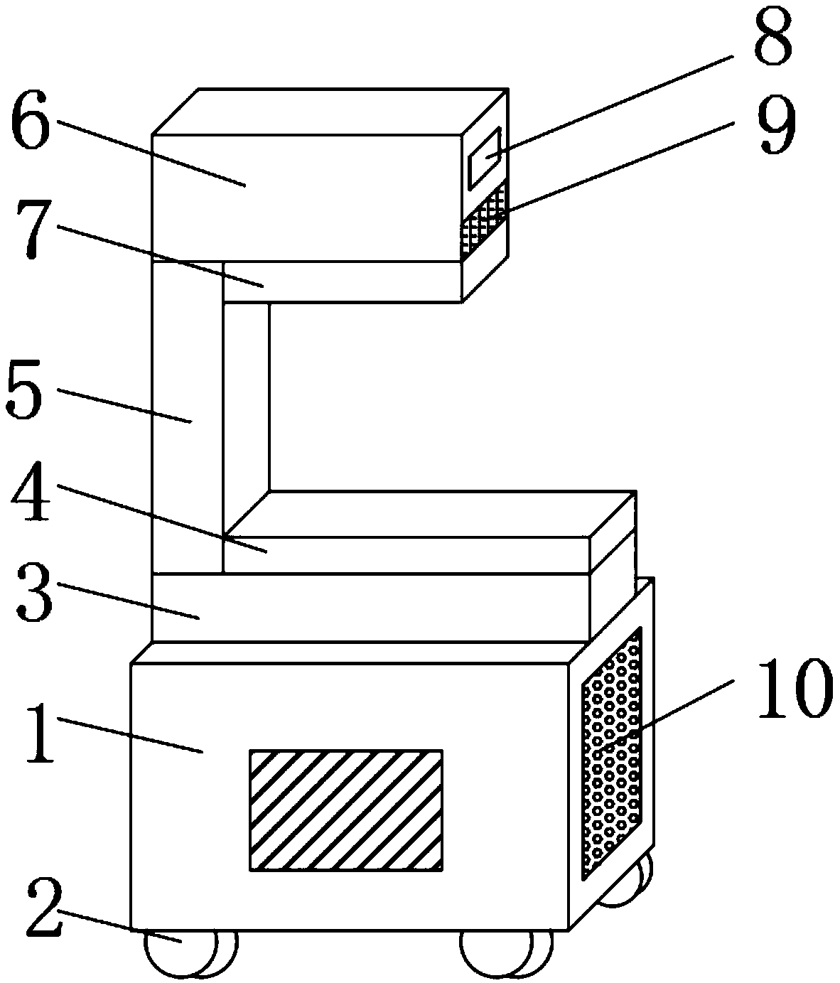
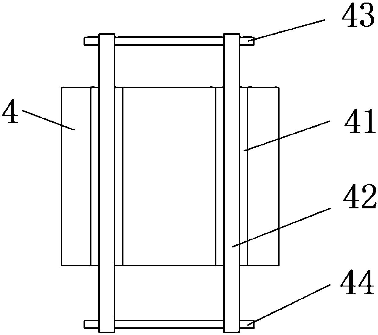
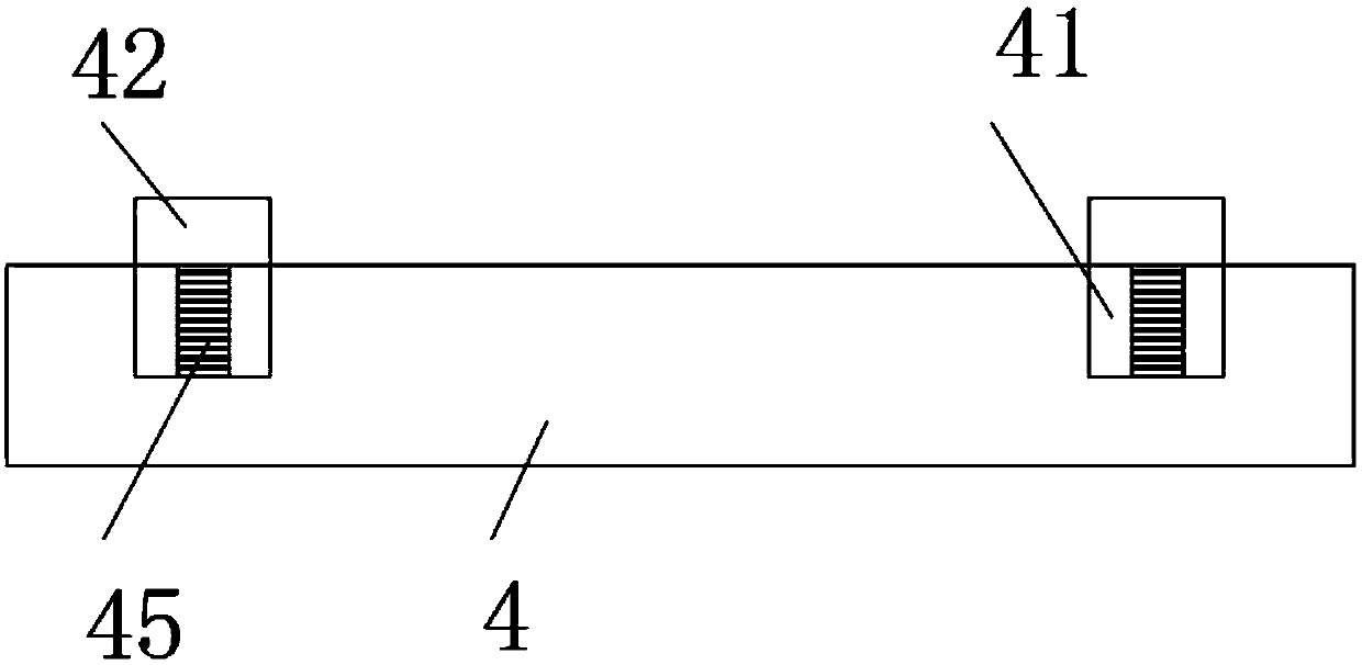
[0029] see Figure 1-7 , the present invention provides a technical solution: a high-efficiency pneumatic stamping device for nano-copper connectors used in factory production, including a body 1, a universal wheel 2 is movable below the body 1, and the body 1 and body 1 are easily moved through the universal wheel 2 The upper end of the base 3 is fixedly installed with the base 3, and the position in the middle of the upper outer surface of the base 3 is mova...


PUM


Abstract

The invention discloses a nano-copper connecting piece efficient pneumatic stamping device for factory production. A machine body is included. Universal wheels are movably installed on a lower portionof the machine body. A base is fixedly installed at an upper end of the machine body. A bearing plate is movably installed in the middle of an outer surface of an upper end of the base, grooves are arranged in two sides of the outer surface of the upper end of the bearing plate, a fixing frame is fixedly installed on one side of the outer surface of the upper end of the base, a pneumatic box is movably installed at the upper end of the fixing frame, and a top pressing plate is movably installed at the lower end of the pneumatic box. By using the nano-copper connecting piece efficient pneumatic stamping device for factory production, the stamping device can carry out continuous stamping through feeding of a conveying belt, labor intensity is reduced while a production capacity is greatly improved, stamping is more stable, chippings on the bearing plate can be removed through a waste gas exhausted by an air cylinder, dust in air is effectively filtered during air inflow, and a situationthat the air cylinder is damaged due to a fact that the dust enters into the air cylinder is avoided.

Description

technical field [0001] The invention relates to the field of pneumatic stamping devices, in particular to a high-efficiency pneumatic stamping device for nano-copper connectors used in factory production. Background technique [0002] Nano-copper is a new type of material made of nano-materials. Its strength is higher than that of ordinary copper, so it is widely used. Nano-copper connectors can connect nano-copper together. Nano-copper connectors are usually produced by stamping devices. Traditional The single-step stamping method not only has low production efficiency, but also cannot control the stability of the product at a high rate. Manual loading and unloading is time-consuming and labor-intensive. The top platen on the stamping device is prone to tilt during stamping, which affects the stamping quality. The debris produced cannot be cleaned up in time, and the dust in the air is easily brought into the cylinder when the cylinder is fed into the air, which easily caus...

Claims


Application Information

Patent Timeline
IPC IPC(8): B21D22/02B21D43/12B21D43/02B21D45/06B30B1/38B30B15/00
CPCB21D22/02B21D43/027B21D43/12B21D45/06B30B1/38B30B15/0052B30B15/0082
Inventor 孙胡虎杰
Owner JIANGYIN SANLING METAL PROD
Learn More