
Method and device for measuring a layer thickness of an object

A technology for objects and equipment, applied in the field of layer thickness of plastic objects, to achieve efficient coverage of bandwidth, avoid redundancy, and avoid related difficulties

Active Publication Date: 2020-03-24
伊诺艾克斯有限公司
View PDF12 Cites 0 Cited by
  • Summary
  • Abstract
  • Description
  • Claims
  • Application Information

AI Technical Summary

Problems solved by technology

[0006] while the resolution of such measurements is limited by still having to separate the two time-shifted signals in the direction of propagation of the electromagnetic radiation

Method used


Image

  • Method and device for measuring a layer thickness of an object
  • Method and device for measuring a layer thickness of an object
  • Method and device for measuring a layer thickness of an object

Examples


Embodiment Construction

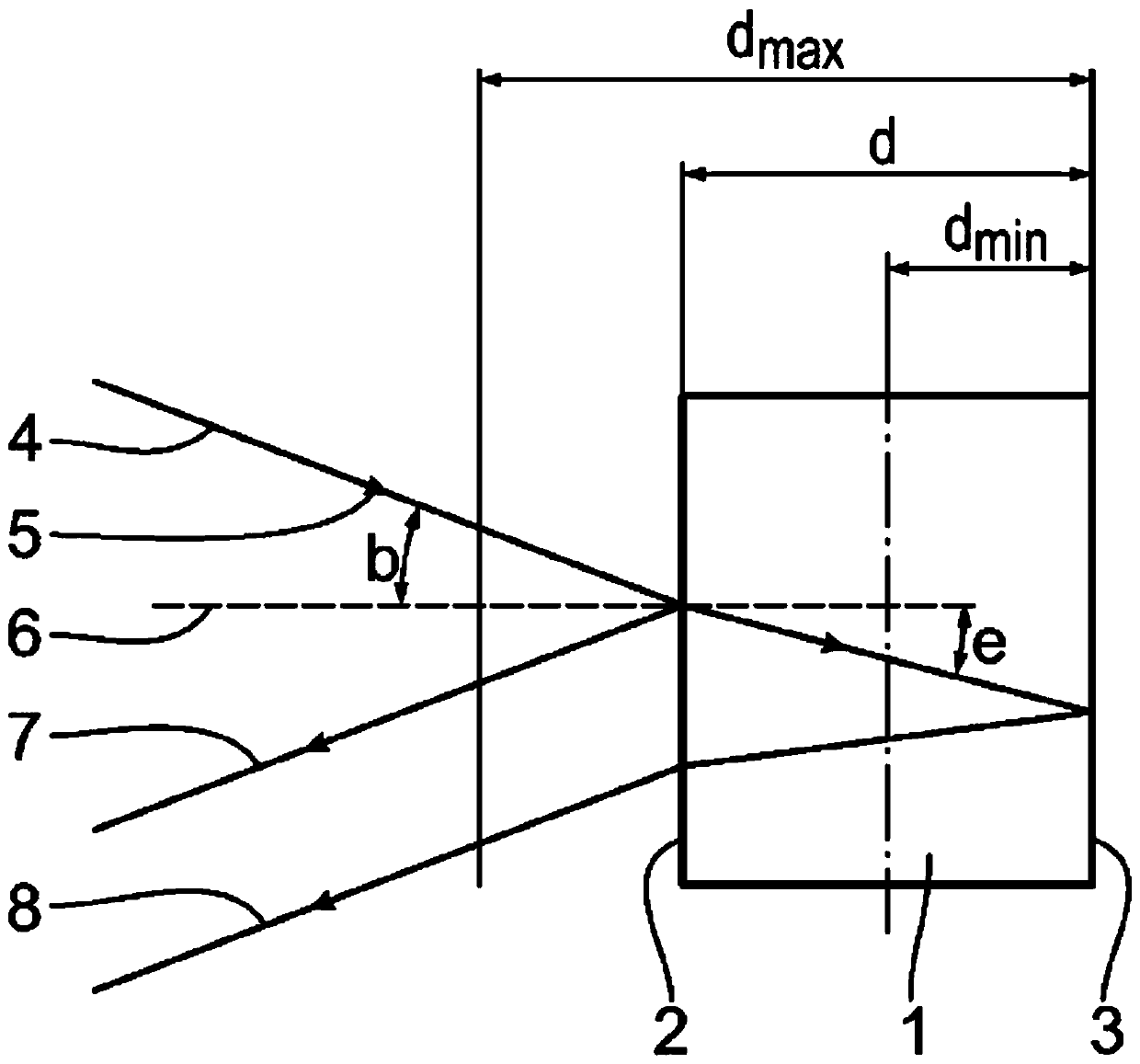
[0063] figure 1 The measurement of the layer thickness d of the object 1 is shown schematically. The object 1 has boundary surfaces 2 , 3 separated by a layer thickness d. The layer thickness d of object 1 is at the minimum layer thickness d min with the maximum layer thickness d max Changes in the range between. Minimum layer thickness d min and the maximum layer thickness d max Indicates the minimum or maximum layer thickness to be measured for the measurement. The refractive index n of the object 1 deviates from the refractive index of the surrounding environment of the object 1 . Typically, measurements are made in air or a vacuum, so the environment has a refractive index of 1.

[0064] In order to measure the layer thickness d of the object 1 , electromagnetic radiation 4 is incident on the boundary surface 2 of the object 1 at an angle of incidence b. The angle of incidence b is defined as the angle between the direction of propagation 5 of the electromagnetic r...


PUM


Abstract

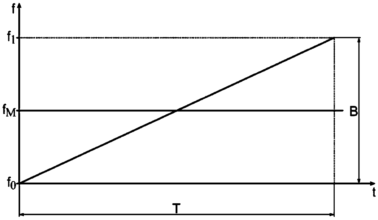
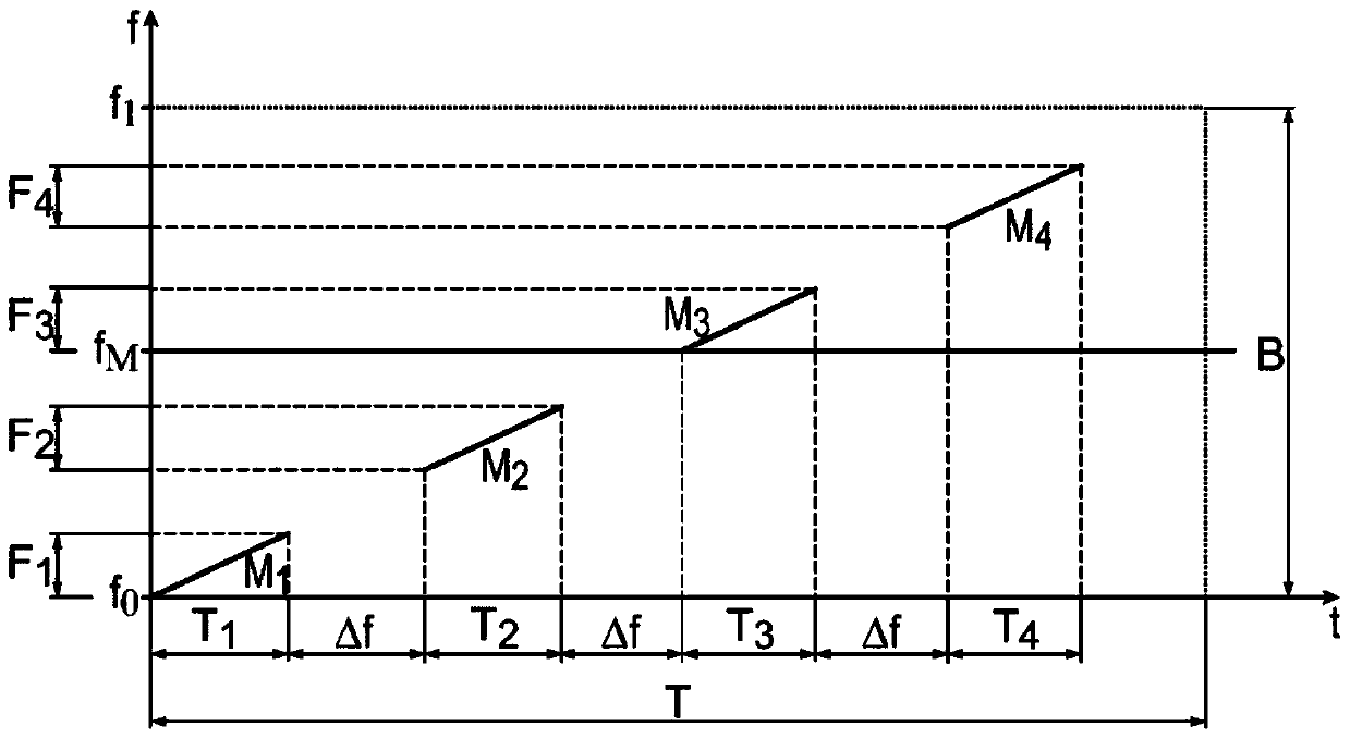
The invention relates to a method and a device for measuring a layer thickness of an object. Firstly, an object which has a layer thickness is provided. Subsequently, at least two measurement steps (Mi) are carried out, wherein in each case electromagnetic radiation with frequencies (f) in a frequency band (Fi) corresponding to the measurement step (Mi) in question is radiated onto the object. Thefrequency bands (Fi) are different partial regions of a bandwidth (B). Secondary radiation emitted by boundary surfaces of the object is detected and a measurement signal corresponding to the measurement step (Mi) is determined. The measurement signals are, according to the frequency bands (Fi) corresponding to the measurement steps (Mi) in question, combined to form an evaluation signal, a basefrequency is determined therefrom, and the layer thickness is calculated. Using the method, a large bandwidth (B) can be realised by means of narrow-band measurement steps (Mi). In so doing, physicallimits of known methods are overcome and the measurement accuracy is increased.

Description

[0001] Cross References to Related Applications [0002] This patent application claims priority from German patent application DE 10 2017 207 648.8, the content of which is incorporated herein by reference. technical field [0003] The invention relates to a method and a device for measuring the layer thickness of objects, in particular plastic objects. Background technique [0004] In industrial manufacturing, for example in quality assurance processes, it is often necessary to measure the exact layer thickness of an object. Layer thickness is the extent of an object between two spaced boundary surfaces of the object. For example the wall thickness of tubes, in particular made of plastic. [0005] For the thickness measurement, for example, terahertz measurement technology using electromagnetic radiation is used. One possibility is the use of pulsed measurement signals, in which case the layer thickness of the object can be deduced from the measured transit time differe...

Claims


Application Information

Patent Timeline
Patent Type & Authority Applications(China)
IPC IPC(8): G01B11/06
CPCG01B11/06G01S13/88G01S13/325G01S13/343G01B15/02
Inventor 本杰明·利陶乔凡尼·肖伯斯蒂芬·克雷姆林
Owner 伊诺艾克斯有限公司
Learn More