
Connection device for a turbocharger, and turbocharger

A technology for connecting equipment and exhaust gas turbines. It is applied in the connection of rods, mechanical equipment, connecting components, etc., which can solve problems such as failures and achieve the effect of reducing the accumulation of stress, tensile stress and compressive stress.

Inactive Publication Date: 2020-03-24
IHI CHARGING SYST INT
View PDF1 Cites 3 Cited by
  • Summary
  • Abstract
  • Description
  • Claims
  • Application Information

AI Technical Summary

Problems solved by technology

The tensile and compressive stresses can cause strains and in the worst case failures due to cracks in operation

Method used


Image

  • Connection device for a turbocharger, and turbocharger
  • Connection device for a turbocharger, and turbocharger
  • Connection device for a turbocharger, and turbocharger

Examples


Embodiment Construction

[0025] The exhaust gas turbocharger, which is not shown in detail, has a first housing section in the form of a flow-through exhaust gas guide section which, during operation of the exhaust gas turbocharger, is supplied by a fluid , usually flowed through by the exhaust gas. The exhaust gases are generally, but not necessarily, combustion products of an internal combustion engine, not shown in detail.

[0026] The exhaust-gas turbocharger is associated with a second housing section, which is designed as a bearing section and serves to support a not-shown impeller of the exhaust-gas turbocharger. The bearing section is positioned between a not shown in detail flow-through air guide section and the exhaust gas guide section of the exhaust gas turbocharger.

[0027] The impeller (not shown in detail) has a compressor rotor (not shown in detail) and a turbine rotor (not shown in detail), which are connected to one another in a rotationally fixed manner by means of a shaft (not sh...


PUM


Abstract

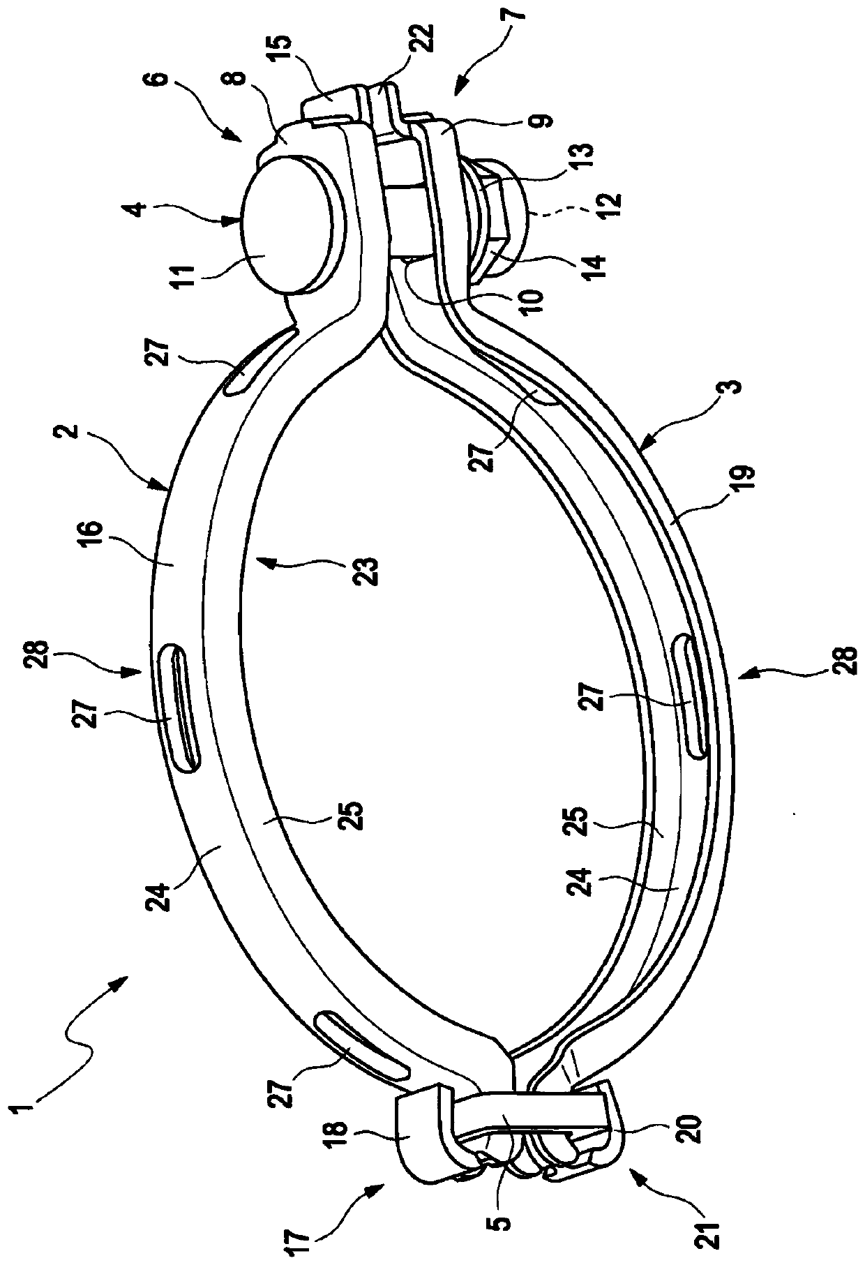
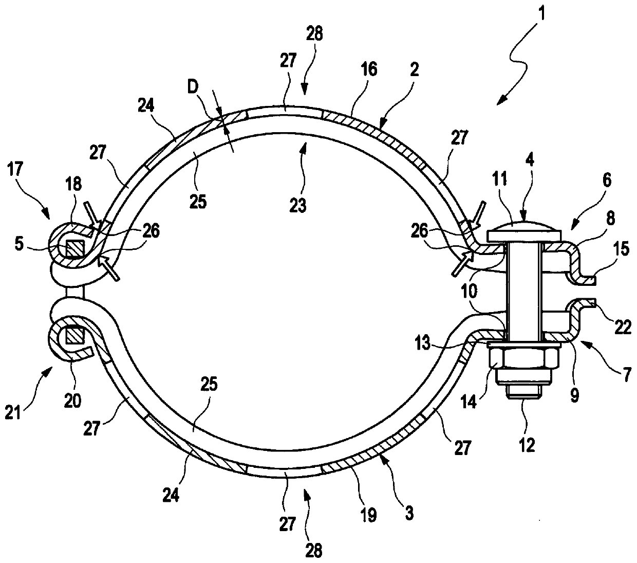
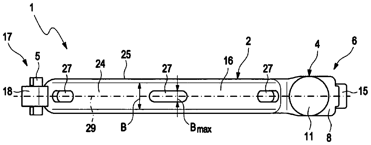
The invention relates to a connection device for a turbocharger, comprising a substantially bent first element (2) and a substantially bent second element (3). The first element (2) and the second element (3) are connected together in a releasable manner in a first end region (6) or a second end region (7) and in a movable manner in a third end region (17) or a fourth end region (21). A first receiving section (16) extends between the first end region (6) and the third end region (17), and a second receiving section (19) extends between the second end region (7) and the fourth end region (21).According to the invention, the connection device (1) has a receiving area (27) formed in the element (2; 3) in order to reduce stress. The invention further relates to a turbocharger comprising a connection device (1).

Description

technical field [0001] The invention relates to a connection device for an exhaust gas turbocharger of the type specified in the preamble of claim 1 . Furthermore, the invention relates to an exhaust gas turbocharger according to the preamble of claim 8 . Background technique [0002] Expediently, the exhaust gas turbocharger is formed from a plurality of housing sections: a first housing section, through which hot gas, usually the exhaust gas of an internal combustion engine, flows through; a second housing section, which is designed to accommodate the The impeller is rotatably mounted in the second housing section and is positioned between the first housing section and a third housing section through which ambient air can usually flow. Between the individual housing sections, the flange surfaces are formed in such a way that they can touch each other, so that the escape of hot air and ambient air is avoided as far as possible. As long as a leak is caused between the flan...

Claims


Application Information

Patent Timeline
Patent Type & Authority Applications(China)
IPC IPC(8): F01N13/18F02B67/10F16B7/18F16L23/08
CPCF01N13/1805F02B37/00F16B7/182F16L23/08Y02T10/12F01D25/243F01D25/26F16B7/0453F16B9/02F16L23/04
Inventor 法哈德·哈德达迪安克劳斯·斯珀林丹尼尔·贾斯特罗伯托·德桑蒂斯
Owner IHI CHARGING SYST INT
Learn More