
A hierarchical path planning method for unmanned vehicles

A path planning, unmanned vehicle technology, applied in vehicle position/route/height control, motor vehicles, instruments, etc., can solve problems such as large amount of calculation, inability to guarantee global convex optimization, and large system operation.

Active Publication Date: 2020-09-01
NAT INNOVATION INST OF DEFENSE TECH PLA ACAD OF MILITARY SCI
View PDF4 Cites 0 Cited by
  • Summary
  • Abstract
  • Description
  • Claims
  • Application Information

AI Technical Summary

Problems solved by technology

[0007] The above-mentioned path planning methods are usually directly solved in a given local environment, which often brings some problems: on the one hand, the solution space is large, which easily leads to a large amount of calculation, which causes a large burden on the system operation; on the other hand , since the distribution of obstacles in the local environment is unknown, path planning in the overall solution space of the local environment cannot be guaranteed mathematically as a global convex optimization problem, which itself may have multiple extreme values. When the environmental perception results are disturbed, the path The planning result may jump on multiple extreme values, resulting in unstable planning results and reducing the safety of unmanned vehicles

Method used


Image

  • A hierarchical path planning method for unmanned vehicles
  • A hierarchical path planning method for unmanned vehicles
  • A hierarchical path planning method for unmanned vehicles

Examples


Embodiment Construction

[0059] The present invention will be described in further detail below in conjunction with the accompanying drawings and specific embodiments. It should be understood that the specific embodiments described here are only used to explain the present invention, not to limit the present invention.

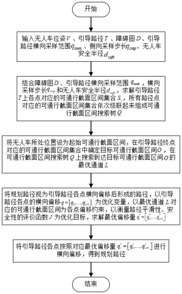
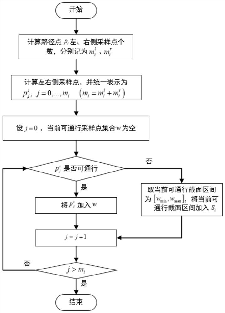
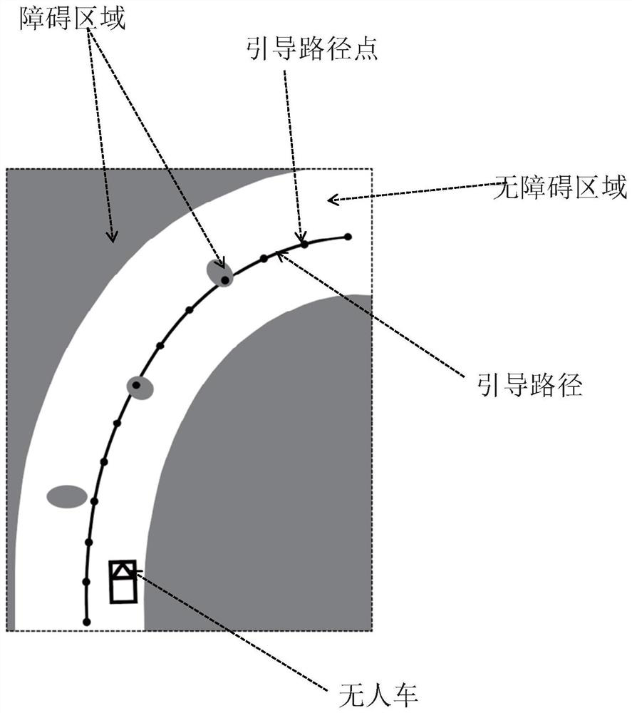
[0060] The present invention proposes a layered path planning method for unmanned vehicles, combined with image 3 specific examples shown, follow the attached figure 1 The flow shown, the specific steps are as follows:

[0061] Step 1: Input the pose V of the unmanned vehicle, the guiding path T, the obstacle map D, and the lateral sampling range q of the guiding path max , horizontal sampling step size q step , unmanned vehicle safety radius d safe . The pose V of the unmanned vehicle includes coordinates and heading angles, which are denoted as V=(x v ,y v , θ v ), where x v ,y v , θ v are the x-coordinate, y-coordinate and heading angle of the unmanned vehicle, which ar...


PUM


Abstract

The invention discloses a layered path planning method for an unmanned vehicle, comprising the following steps: (1) inputting parameters such as the position and posture of the unmanned vehicle, a guiding path, and an obstacle map; (2) solving the passable section interval according to the guiding path and the obstacle map Search tree; (3) Determine the target passable section interval in the passable section interval set corresponding to the end point of the guidance path, and search for the optimal passage to the target passable section interval on the passable section interval search tree; (4) use the most The passable section interval in the optimal channel is an offset constraint, and the optimal offset is solved with path smoothness and safety as the optimization goal; (5) each point of the guided path is laterally offset according to the corresponding optimal offset, Get the planned path. The present invention can avoid fine-grained search in the entire local planning range, reduce the amount of calculation, and at the same time use the optimal channel to constrain the solution space of the final planning path, thereby improving the stability and temporal-spatial consistency of planning results.

Description

technical field [0001] The invention belongs to the field of path planning for unmanned vehicles, and in particular relates to a layered path planning method for unmanned vehicles. Background technique [0002] Unmanned vehicles have great potential in reducing traffic accidents, saving energy, and improving transportation efficiency, and have become a research hotspot for governments and scientific research institutions in various countries. The path planning of the unmanned vehicle is one of the key technologies to realize its automatic driving. Its purpose is to find a safe path for the unmanned vehicle to gradually lead to the target position in the environment. [0003] The prior art discloses a device and method for local path planning of unmanned vehicles (application number is 201110007154.X), the device includes an environment perception device, a repulsion calculation device, a gravitational calculation device, a resultant force direction angle calculation device a...

Claims


Application Information

Patent Timeline
Patent Type & Authority Patents(China)
IPC IPC(8): G05D1/02
CPCG05D1/0214G05D1/0221G05D1/0276G05D2201/0212G05D1/0217
Inventor 朱琪商尔科戴斌肖良聂一鸣赵大伟
Owner NAT INNOVATION INST OF DEFENSE TECH PLA ACAD OF MILITARY SCI
Learn More