
Automatic manufacturing device of blood smear

A technology for making a device and a blood smear, which is applied in the field of medical devices, can solve the problems of large workload of manually making smears, difficult to meet the requirements of testing, and reduced testing efficiency, and achieves improved production efficiency, convenient removal, and accelerated drying. effect of speed

Active Publication Date: 2020-03-24
THE SECOND AFFILIATED HOSPITAL ARMY MEDICAL UNIV
View PDF7 Cites 6 Cited by
  • Summary
  • Abstract
  • Description
  • Claims
  • Application Information

AI Technical Summary

Problems solved by technology

However, this method is only suitable for the production of a single or a small number of smears, and it is more common in clinical practice
However, using this production method for blood smears, considering the heavy workload and low efficiency of manually making smears, when the detection workload is heavy, this way of manually making smears will greatly reduce the detection work efficiency , it is difficult to meet the detection requirements

Method used


Image

  • Automatic manufacturing device of blood smear
  • Automatic manufacturing device of blood smear
  • Automatic manufacturing device of blood smear

Examples


Embodiment 1

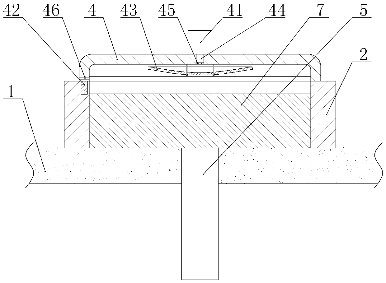
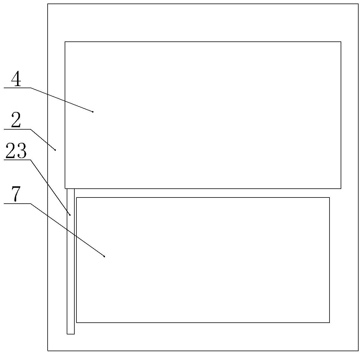
[0037] Automatic production equipment for blood smears, such as figure 1 and figure 2As shown, it includes a frame, a transmission unit, a dropper 61, a pusher, a drying tube and a dyeing tube 68. The transmission unit includes a conveyor belt 1 and a transmission drive. The transmission drive in this embodiment selects a geared motor, and the transmission drive It is fixed on the frame by bolts, and the left and right ends of the frame are equipped with rotating shafts. The rotating shaft runs through the frame and there are bearings between the two ends of the rotating shaft and the frame. A driven gear is fixed on the top through a flat key, and an incomplete gear meshing with the driven gear is connected to the output shaft of the rotating drive part through a coupling, and the rotating drive part drives the conveyor belt 1 to rotate intermittently clockwise.

[0038] On the conveyor belt 1, several placement plates 7 are arranged at uniform intervals along the length di...

Embodiment 2

[0050] On the basis of Example 1, such as Figure 4 , Figure 5 and Figure 6 As shown, the placement plate 7 in this embodiment is provided with a negative pressure chamber and a hot gas chamber 75 located below the negative pressure chamber. A second piston 71 is slidably sealed in the negative pressure chamber. The second piston 71 is arranged laterally and the second piston 71 divides the negative pressure chamber into an upper adsorption chamber 72 and a lower exhaust chamber 74. The top of the adsorption chamber 72 is provided with a number of adsorption holes 73, and the left wall of the exhaust chamber 74 is provided with a first pressure relief hole 21. The wall is provided with a second pressure relief hole 76 communicating with the first pressure relief hole 21, and a second spring is arranged in the exhaust chamber 74, and the two ends of the second spring are respectively welded to the second piston 71 and the bottom of the exhaust chamber 74.

[0051] Two teles...


PUM


Abstract

The invention relates to the field of medical instruments, and particularly discloses an automatic manufacturing device of a blood smear. The device comprises a conveying unit, a dropping pipette, a pushing piece, a drying tube and a dyeing tube. The conveying unit comprises a conveying belt and a conveying driving piece, a plurality of placing plates are arranged on the conveying belt at intervals, and annular baffles are arranged at the peripheries of the placing plates and are fixed to the conveying belt. The placing plates are slidably connected with the baffles, and sliding rods are fixedto the bottoms of the placing plates and penetrate through the conveying belt,the dropping pipette and the dyeing tube are both vertically arranged, and the pushing piece, the dropping pipette, the drying tube and the dyeing tube are all located on the placing plates. The device disclosed by the invention can be used for automatically manufacturing the blood smear so as to improve the manufacturing efficiency of the blood smear.

Description

technical field [0001] The invention relates to the field of medical equipment, in particular to an automatic production device for a blood smear. Background technique [0002] The production of smears is generally to use a pipette to take samples and drop them on the glass slide, and then push the samples away with the help of a clean pusher, and then stain the samples after they are dry. However, this method is only suitable for the production of a single or a small number of smears, which is more common in clinical practice. However, using this production method for blood smears, considering the heavy workload and low efficiency of manually making smears, when the detection workload is heavy, this way of manually making smears will greatly reduce the detection work efficiency , it is difficult to meet the detection requirements. Contents of the invention [0003] The object of the present invention is to provide a device for automatically making blood smears, so as to...

Claims


Application Information

Patent Timeline
IPC IPC(8): G01N1/28G01N1/30
CPCG01N1/2813G01N1/30
Inventor 杨蛟刘琳琳沈坤园李志强曾文雨杨柳
Owner THE SECOND AFFILIATED HOSPITAL ARMY MEDICAL UNIV
Learn More