
Scrap collecting structure of water conservancy pipeline cutting device

A pipe cutting and water conservancy technology, applied in metal processing equipment, maintenance and safety accessories, metal processing machinery parts, etc., can solve the problems of inconvenient chip evacuation, inconvenient chip collection, and impact on collection efficiency, etc. Achieve the effect of preventing self-falling, increasing flexibility, and increasing collection efficiency

Active Publication Date: 2020-03-24
凤阳县天龙水利建筑工程有限公司
View PDF15 Cites 0 Cited by
  • Summary
  • Abstract
  • Description
  • Claims
  • Application Information

AI Technical Summary

Problems solved by technology

[0003] At present, water conservancy pipelines are cut by a cutting device, and the bottom of the cutting device is usually equipped with a debris collection structure, which is used to collect the debris generated during pipe cutting, keep the cutting environment clean, and can also be recycled. The existing water conservancy When the pipe cutting device is working, the chip outlet at the bottom cannot discharge chips in an orderly manner, and the feed hopper of the chip collection structure usually cannot be connected to the chip outlet position, causing the chips to scatter out, which is not convenient for chip collection. Greatly affect the collection efficiency

Method used


Image

  • Scrap collecting structure of water conservancy pipeline cutting device
  • Scrap collecting structure of water conservancy pipeline cutting device
  • Scrap collecting structure of water conservancy pipeline cutting device

Examples


Embodiment 1

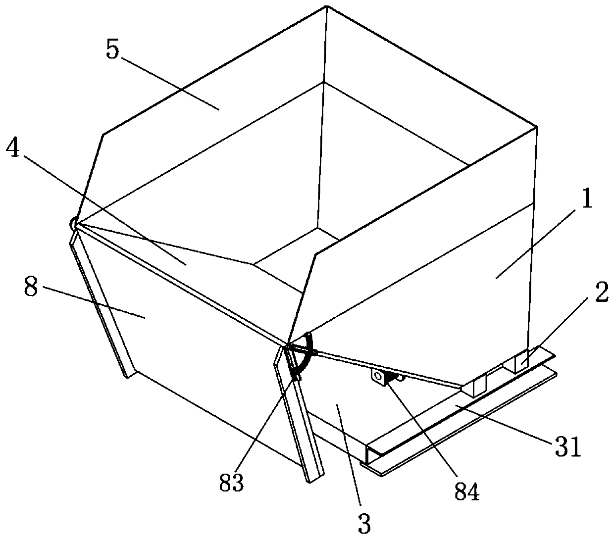
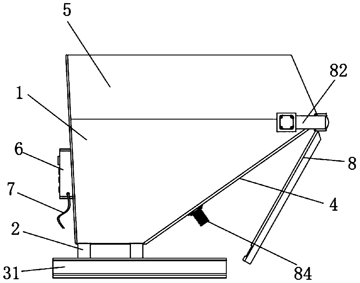
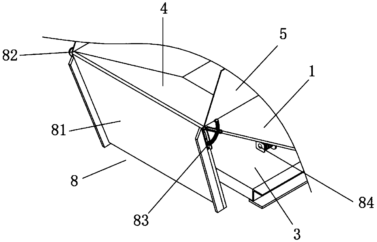
[0032] see Figure 1-2 As shown, the present invention provides a debris collection structure fire extinguisher fixing structure for a water conservancy pipeline cutting device through improvement, including a debris storage bin 1, a connecting bracket 2, a supporting base plate 3, a plate side frame 31, a chipping plate 4, Cover 5, control box 6, power cord 7 and auxiliary chip feeding mechanism 8, connecting brackets 2 are respectively provided on both sides of the bottom of the chip storage bin 1, a board side frame 31 is respectively provided at both ends of the support base plate 3, and the chip storage bin 1 The bottom is fixed with the plate side frame 31 supporting the side end of the bottom plate 3 through the connecting bracket 2. The front end of the chip storage bin 1 is a chip dropping plate 4 and is not an integral structure. In order to prevent debris from splashing out when falling, a control box 6 is provided in the middle of the rear end of the chip storage b...

Embodiment 2

[0038] The present invention provides a debris collection structure of a water conservancy pipeline cutting device through improvement. A storage battery is provided inside the control box 6, which can be charged and stored in advance through the power cord 7 to keep the equipment running. A groove is provided, and the groove matches the buffer plate 845 in the reset buffer structure 84, so that the auxiliary chip plate 81 corresponds to the buffer plate 845 when falling, and the buffer plate 845 absorbs the buffer force, and the driving motor 827 outputs The shaft is fixed to one end of the transmission shaft 826, and the other end of the transmission shaft 826 is fixed to the inner surface of the gear protection shell 824. After the drive motor 827 works, the transmission shaft 826 is driven to rotate by the output shaft, and the positioning frame bar 831 and the movable fork 833 bottom end surface is provided with installation fixed edge, is convenient to be fixed with chip ...


PUM


Abstract

The invention discloses a scrap collecting structure of a water conservancy pipeline cutting device. The scrap collecting structure comprises a scrap storage bin, connecting supports, a supporting bottom plate, plate edge frames, a scrap falling plate, a blocking cover, a control box, a power line and an auxiliary scrap feeding mechanism. The connecting supports are respectively arranged on the two sides of the bottom of the scrap storage bin. The two ends of the supporting bottom plate are respectively provided with one plate edge frame. The bottom of the scrap storage bin is fixed to the plate edge frame at the side end of the supporting bottom plate through the connecting support. The front end of the scrap storage bin is provided with the scrap falling plate and is not of an integratedstructure. The auxiliary scrap feeding mechanism is arranged at the front end of the scrap falling plate, the auxiliary scrap falling plate is driven by the rotating mechanism to turn over to be parallel to the scrap falling plate, and angle positioning is conducted through the angle positioning mechanism, the area of the scrap falling plate is increased, the auxiliary scrap falling plate can bein direct butting with the scrap falling opening in the bottom of the cutting device, the scraps can better enter the scrap storage bin and the collecting efficiency of the scraps is improved.

Description

technical field [0001] The invention relates to the related field of cutting devices, in particular to a debris collection structure of a water conservancy pipeline cutting device. Background technique [0002] Water conservancy engineering is a project built to control and allocate natural surface water and groundwater to achieve the purpose of eliminating harm and rejuvenating profits. It is also called water engineering. Water is an indispensable and precious resource for human production and life, but its natural existence The state does not fully meet the needs of human beings. Only by building water conservancy projects can water flow be controlled, floods prevented, and water volume adjusted and distributed to meet the needs of people's life and production for water resources. The implementation of water conservancy projects is inseparable from Pipes are laid, and pipes need to be cut during actual use. [0003] At present, water conservancy pipelines are cut by a cu...

Claims


Application Information

Patent Timeline
Patent Type & Authority Applications(China)
IPC IPC(8): B23Q11/00
CPCB23Q11/0042
Inventor 王伟平
Owner 凤阳县天龙水利建筑工程有限公司
Learn More