A stamping and forming system for the manufacture of electric control cabinet sheet metal panels

A technology for electrical control cabinets and sheet metal panels, which is applied in the field of stamping and forming systems for the manufacture of electrical control cabinet sheet metal panels, which can solve problems such as waste of cost, different sizes of intermediate positioning holes, increased stamping times, and hidden dangers of product scrapping, so as to reduce the hidden danger of scrapping , reduce the number of punching times, and increase the effect of scrapping hidden dangers

Active Publication Date: 2021-04-09
SUZHOU XINENG ENVIRONMENTAL SCI & TECH CO LTD
View PDF12 Cites 0 Cited by
  • Summary
  • Abstract
  • Description
  • Claims
  • Application Information

AI Technical Summary

Problems solved by technology

[0002] Stamping processing is the power of conventional or special stamping equipment, so that the sheet metal is directly subjected to deformation force and deformed in the mold, so as to obtain product parts with a certain shape, size and performance. Among them, the sheet metal in the electrical control cabinet The panel is completed with a stamping process license, but the existing electrical control cabinet sheet metal panels still have certain deficiencies in the manufacturing process
[0003] The sheet metal panels of the existing electrical control cabinets often have the following problems in the actual stamping process: a: In the stamping process of the existing electrical control cabinets, in order to achieve the required shape, a part is often fixed and stamped multiple times to obtain the required shape. shape, but the increase in stamping times also greatly increases the hidden danger of product scrapping; b: when the existing electrical control cabinet is punched, it may be because the size of the middle positioning hole is different, resulting in the need to replace the parts during processing. work, waste of time, waste of cost

Method used


Image

  • A stamping and forming system for the manufacture of electric control cabinet sheet metal panels
  • A stamping and forming system for the manufacture of electric control cabinet sheet metal panels
  • A stamping and forming system for the manufacture of electric control cabinet sheet metal panels

Examples


Embodiment Construction

[0028] In order to make the technical means realized by the present invention, creative features, goals and effects easy to understand, the following combination Figure 1 to Figure 8 , to further elaborate the present invention.

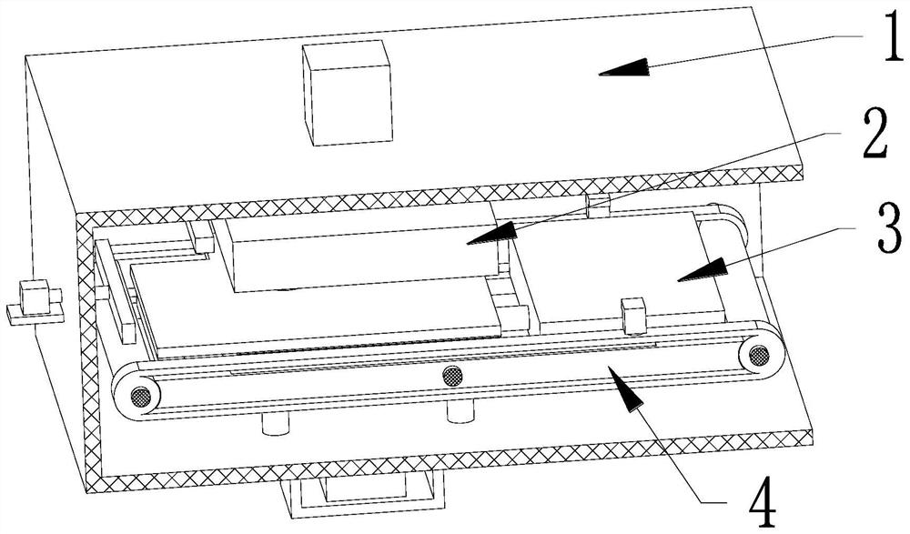
[0029] A stamping and forming system for the manufacture of electric control cabinet sheet metal panels, including a mounting frame 1, a stamping device 2, a supporting device 3 and a transmission device 4, and the mounting frame 1 is provided with a stamping device 2 and a supporting device 3 sequentially from top to bottom. The outer end of the device 3 is provided with a transmission device 4, and the transmission device 4 is installed on the mounting frame 1, wherein:

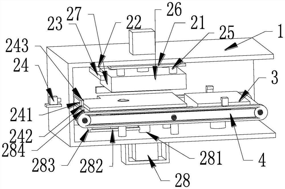
[0030] The stamping device 2 includes a hydraulic cylinder A, a connecting plate 21, a connecting rod 22, a forming pressing plate 23, an edge pushing mechanism 24, a connecting column A25, a pressing plate 26, a pre-bending mechanism 27 and a top edge mechanism 28, and the hydra...


PUM


Abstract

The invention relates to a stamping and forming system for manufacturing sheet metal panels of electric control cabinets, including a mounting frame, a stamping device, a supporting device and a transmission device. The stamping device and the supporting device are sequentially arranged inside the mounting frame from top to bottom, and the outer end of the supporting device is arranged There is a transmission device, and the transmission device is installed on the mounting frame. The present invention can solve the following problems that often exist in the actual production process of the sheet metal panel of the existing electrical control cabinet: a: In the stamping process of the existing electrical control cabinet, in order to achieve the required shape, a part is often fixed and stamped multiple times to obtain the desired shape, but the increase in the number of stampings also greatly increases the hidden danger of product scrapping; b: when stamping the existing electrical control cabinet, it may be due to the The size of the positioning holes is different, resulting in the need to replace the parts during processing, which is a waste of time and cost.

Description

technical field [0001] The invention relates to the technical field of stamping processing of sheet metal parts of electric cabinets, in particular to a stamping forming system for manufacturing sheet metal panels of electric control cabinets. Background technique [0002] Stamping processing is the power of conventional or special stamping equipment, so that the sheet metal is directly subjected to deformation force and deformed in the mold, so as to obtain product parts with a certain shape, size and performance. Among them, the sheet metal in the electrical control cabinet The panel is completed with a stamping process license, but the existing electrical control cabinet sheet metal panels still have certain deficiencies in the manufacturing process. [0003] The sheet metal panels of the existing electrical control cabinets often have the following problems in the actual stamping process: a: In the stamping process of the existing electrical control cabinets, in order to...

Claims


Application Information

Patent Timeline
Patent Type & Authority Patents(China)
IPC IPC(8): B21D19/08B21D43/00B21D43/18
CPCB21D19/08B21D43/003B21D43/18
Inventor 张景龙李翔
Owner SUZHOU XINENG ENVIRONMENTAL SCI & TECH CO LTD
Why Eureka
Try Eureka