Parallel IGBT driving method of power electronic equipment

A technology of power electronics and driving method, which is applied in the field of parallel IGBT driving, can solve the problems of large transmission time jitter and inapplicability, and achieves the improvement of turn-on and turn-off capability, simple solution, and suppression of static and dynamic uneven currents. Effect

Inactive Publication Date: 2020-03-17
NR ELECTRIC CO LTD +3
View PDF5 Cites 2 Cited by
  • Summary
  • Abstract
  • Description
  • Claims
  • Application Information

AI Technical Summary

Problems solved by technology

Due to the differences in the parameters of optical isolation devices, the transmission time jitter is large, and it is not suitable for occasions with high synchronization requirements.
In addition, the existing single-channel IGBT drive technology is generally suitable for the frequent turn-on and turn-off of the IGBT, but it is not suitable for the occasional turn-on or turn-off of the high-current condition, and the turn-off capability of the IGBT needs to be improved and optimized

Method used


Image

  • Parallel IGBT driving method of power electronic equipment
  • Parallel IGBT driving method of power electronic equipment

Examples


Embodiment Construction

[0023] The technical solutions and beneficial effects of the present invention will be described in detail below in conjunction with the accompanying drawings.

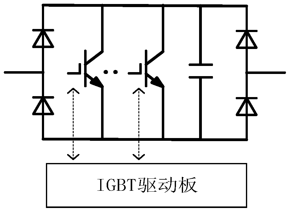
[0024] As the current level continues to increase, power electronic equipment requires multiple IGBTs to be directly connected in parallel to increase the ability of the device to turn on or turn off the current. figure 2 It is a valve group topology aimed at by a parallel IGBT driving method of power electronic equipment in the present invention. The valve group in the figure includes at least two parallel IGBTs, and the number of parallel IGBTs is closely related to the device current parameters. In order to better control parallel IGBT devices, it is necessary to configure a special driver board as the control interface of the IGBT.

[0025] figure 1 Shown is an IGBT driving method for the above-mentioned power electronic device topology, including the following steps:

[0026] Step 1: Configure the number of p...


PUM


Abstract

The invention discloses a parallel IGBT driving method of power electronic equipment. The parallel IGBT driving method comprises the steps of configuring the driving number of parallel IGBTs, selecting a driving connection mode of the parallel IGBTs, setting IGBT gate voltage and driving resistance, and determining a graded turn-off mode of the IGBTs. According to the driving scheme, optical device isolation is not needed, non-delay synchronous driving of the parallel IGBT devices is guaranteed, and static and dynamic non-uniform currents are restrained; the single IGBT drive greatly improvesthe conduction and turn-off current capability of a single IGBT through gate voltage enhancement, drive resistor setting, hierarchical turn-off control and the like, reduces di / dt and overvoltage in the IGBT turn-off process, and guarantees the reliable operation of the IGBT. The IGBT drive circuit is simple in driving, flexible in control and quick in action, the IGBT parallel number can be flexibly configured according to a current target value, the capacity utilization rate of a single IGBT is high, and the IGBT drive circuit is suitable for large-current on-off valve group occasions of different voltage levels.

Description

technical field [0001] The invention belongs to the technical field of power electronics, and in particular relates to a parallel IGBT driving method of power electronic equipment. Background technique [0002] Power electronic equipment is a kind of electrical equipment based on fully controlled power semiconductor devices for electric energy conversion. It is composed of multiple sub-units connected in series and parallel, and is monitored and controlled by the control device at the same time. It is a flexible DC converter valve, DC The core components of high-power power electronic equipment such as circuit breakers and static synchronous compensators. [0003] Power electronic equipment based on power device valve groups and control devices has been widely used in transmission and distribution grids of various voltage levels, various industrial and mining enterprises, wind power, photovoltaic power plants, DC transmission converter stations and other scenarios; in order ...

Claims


Application Information

Patent Timeline
IPC IPC(8): H02M1/088
CPCH02M1/088
Inventor 王文杰文卫兵谢晔源石岩杨兵杨勇石巍吕玮李乐乐李明樊纪超刘亚萍李琦王加龙魏争
Owner NR ELECTRIC CO LTD
Why Eureka
Try Eureka