
Radiation test method and system

A test method and test system technology, applied in the computer field, can solve the problems of insufficient accuracy of test results and low test efficiency

Pending Publication Date: 2020-03-17
SUZHOU LANGCHAO INTELLIGENT TECH CO LTD
View PDF5 Cites 0 Cited by
  • Summary
  • Abstract
  • Description
  • Claims
  • Application Information

AI Technical Summary

Problems solved by technology

[0005] This application provides a radiation testing method and system to solve the problems of low test efficiency and insufficient accuracy of test results in the radiation testing method in the prior art

Method used


Image

  • Radiation test method and system
  • Radiation test method and system

Examples


Embodiment 1

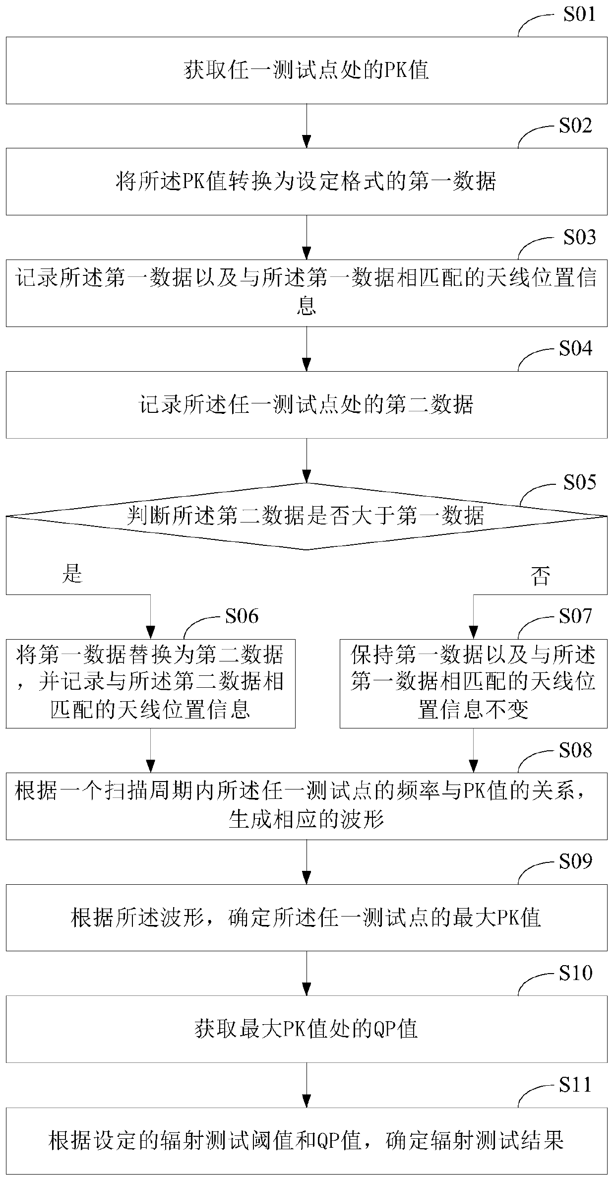
[0054] see figure 1 , figure 1 It is a schematic flow chart of a radiation testing method provided in the embodiment of the present application, which is composed of figure 1 It can be seen that the radiation testing method in this embodiment mainly includes the following processes:

[0055] S01: Obtain the PK value at any test point.

[0056] It is usually necessary to capture multiple test points during the radiation test. After determining the number of test points to be captured, the radiation test results of these test points are used as the overall radiation test results. In this embodiment, the number of grabbing test points is 10-12, which can not only ensure the comprehensive measurement of the radiation intensity of the device under test, but also not too many, which is beneficial to save test time and improve test efficiency.

[0057] After determining the test point to be captured, first obtain the PK value at any test point by scanning the antenna.

[0058] Af...

Embodiment 2

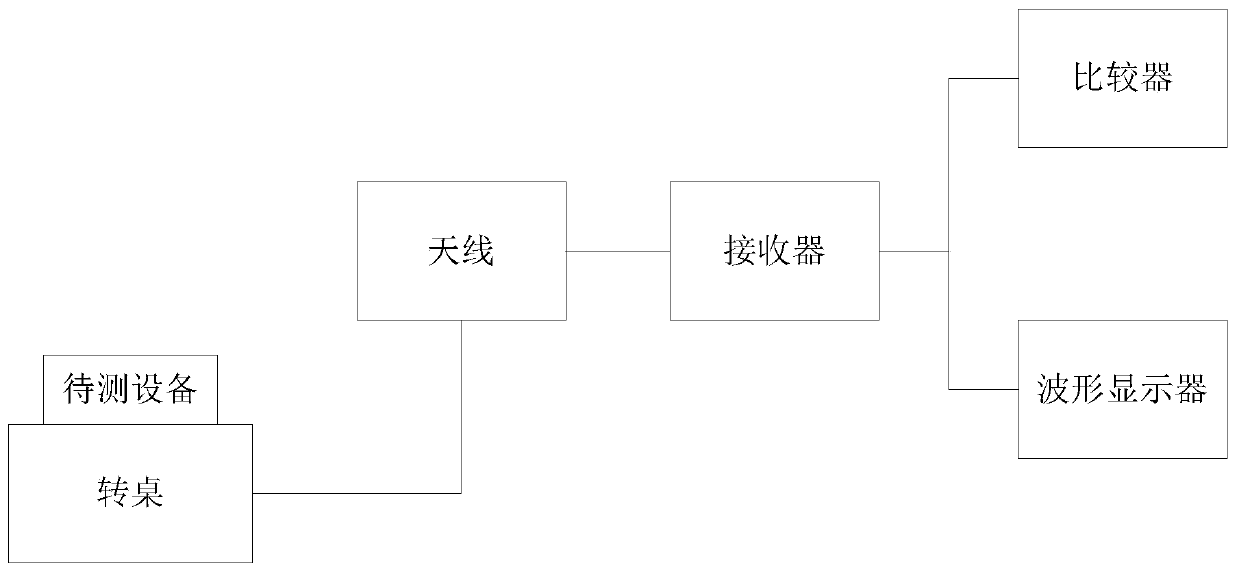
[0080] exist figure 1 On the basis of the illustrated embodiment see figure 2 , figure 2 It is a schematic structural diagram of a radiation testing system provided in the embodiment of the present application. Depend on figure 2 It can be seen that the radiation testing system in this embodiment mainly includes: an antenna, a turntable, a receiver, a comparator, and a waveform display. Among them, the equipment to be tested is fixed on the turntable, the horizontal distance between the antenna and the turntable is fixed, the vertical distance between the antenna and the turntable is variable, the receiver is connected to the antenna, the comparator is connected to the receiver, and the radiation test system Set in a dark room, the radiation test system is applied to the equipment under test with a frequency range of 30MHz-1GHz. The antenna is used to scan the device under test, and the receiver is used to receive the PK value at any test point from the antenna, process...


PUM


Abstract

The application discloses a radiation test method and system. The method comprises the following steps: acquiring a PK value at any test point, converting the PK value into first data in a set format,and recording the first data and antenna position information; recording second data at any test point, replacing the first data with the second data and recording antenna position information underthe condition that the second data are greater than the first data; otherwise, keeping the first data and the antenna position of the first data, generating a waveform according to a relationship between the frequency and the PK value of any test point in a scanning period; determining a maximum PK value and a QP maximum value of any test point according to the waveform; and comparing the QP maximum value with a radiation test threshold value to determine a radiation test result. In addition, the system comprises an antenna, a rotary table, a receiver, a comparator and a waveform display device; a to-be-tested device is fixedly arranged on the rotary table; the receiver is in communication connection with the antenna; and the comparator is in communication connection with the receiver. According to the application, the test efficiency and the accuracy of the test result can be greatly improved.

Description

technical field [0001] The present application relates to the field of computer technology, in particular to a radiation testing method and system. Background technique [0002] EMC (Electro Magnetic Compatibility, Electromagnetic Compatibility) testing is a basic test for the export of electrical products, and radiation testing is an important item in EMC testing. The radiation test in the computer field mainly includes different frequency tests. Usually, 30MHz-1GHz is a test interval, and the test interval higher than 1GHz is called high-frequency radiation test. How to conduct radiation tests on computers or servers to obtain their electromagnetic compatibility characteristics is an important technical issue. [0003] Taking the test in the frequency range of 30MHz-1GHz as an example, the current radiation test method for computers or servers usually uses the method of finding the maximum value of PK twice. Specifically, the antenna scans the device under test 360° at 1...

Claims


Application Information

Patent Timeline
IPC IPC(8): G01R29/08
CPCG01R29/0814G01R29/0871
Inventor 李军阳
Owner SUZHOU LANGCHAO INTELLIGENT TECH CO LTD
Learn More