Electromechanical part stamping device

A technology for stamping devices and accessories, which is applied in the field of stamping devices for electromechanical accessories. It can solve the problems of affecting the stamping speed of accessories, unexpected shaking of the stamping plate, and consuming a lot of time, so as to achieve the effects of improving quality, improving applicability, and increasing stamping speed.

Inactive Publication Date: 2020-03-17
HUBEI POLYTECHNIC UNIV
View PDF1 Cites 0 Cited by
  • Summary
  • Abstract
  • Description
  • Claims
  • Application Information

AI Technical Summary

Problems solved by technology

[0004] Although the above-mentioned patented solution solves the shortcomings of the traditional electromechanical accessories stamping device, there are still some shortcomings in this solution. Poor; 2. The existing electromechanical parts stamping device is easy to absorb the finished parts on the inner wall of the mold after stamping, which takes a lot of time to take out, which seriously affects the stamping speed of the parts; 3. The existing electromechanical parts stamping device is in the stamping process. The stamping plate is prone to accidental shaking, which seriously affects the quality of the finished parts; for this reason, we propose a stamping device for electromechanical parts to solve the problems mentioned in the background technology above

Method used


Image

  • Electromechanical part stamping device
  • Electromechanical part stamping device
  • Electromechanical part stamping device

Examples


Embodiment Construction

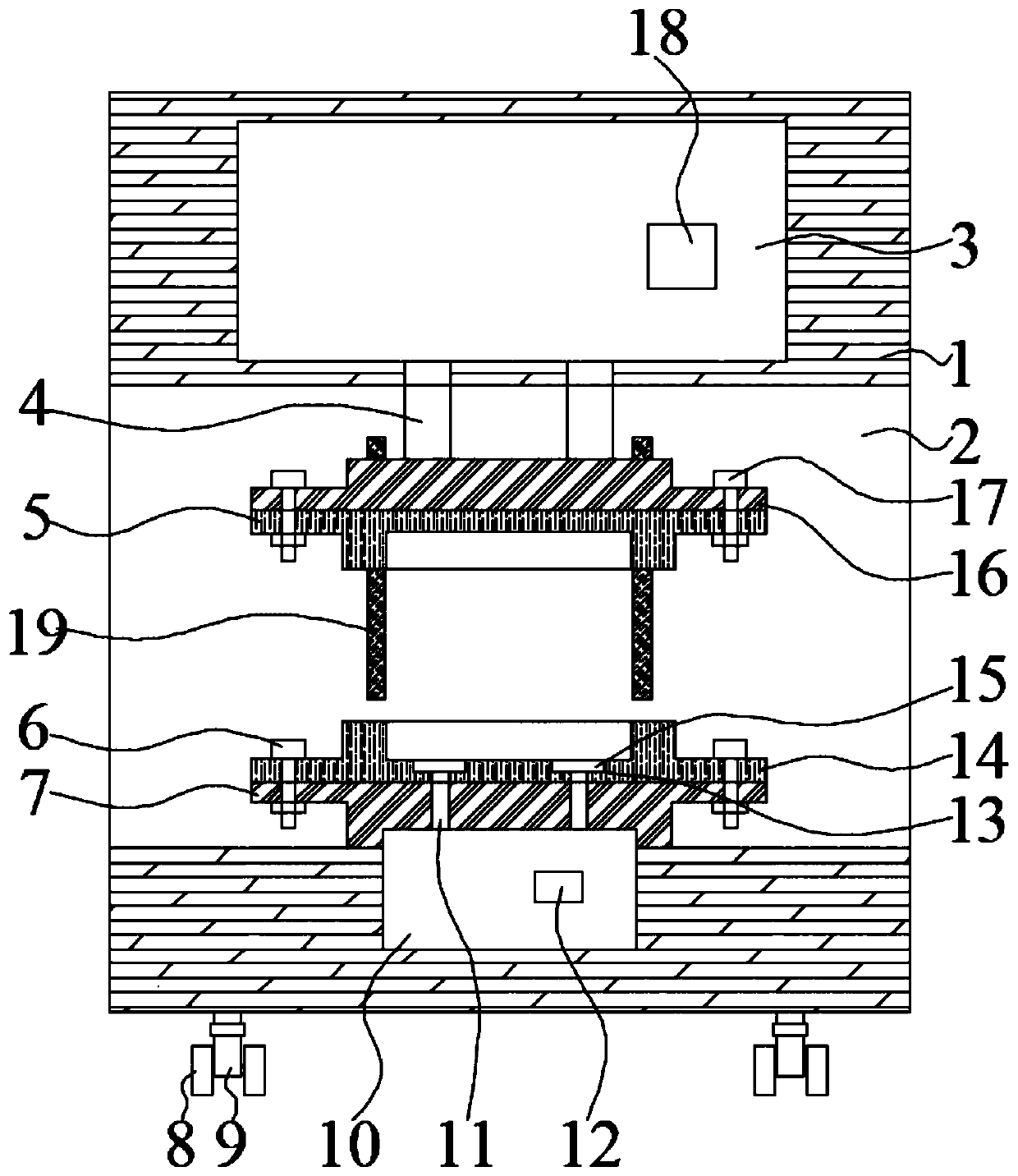
[0021] In order to make the purpose, technical solutions and advantages of the present invention clearer, the present invention will be further described in detail below in conjunction with the accompanying drawings. Obviously, the described embodiments are only some of the embodiments of the present invention, rather than all of them. Based on the embodiments of the present invention, all other embodiments obtained by persons of ordinary skill in the art without making creative efforts belong to the protection scope of the present invention.

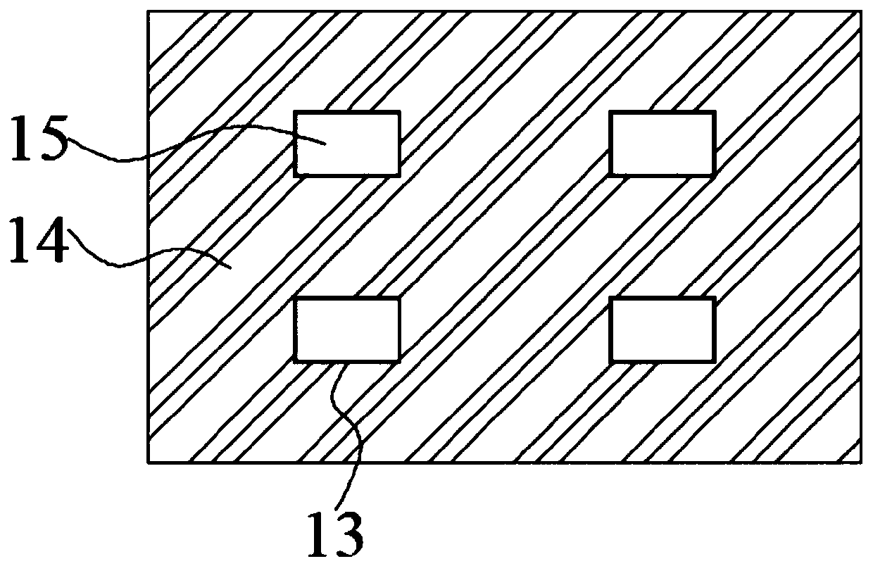
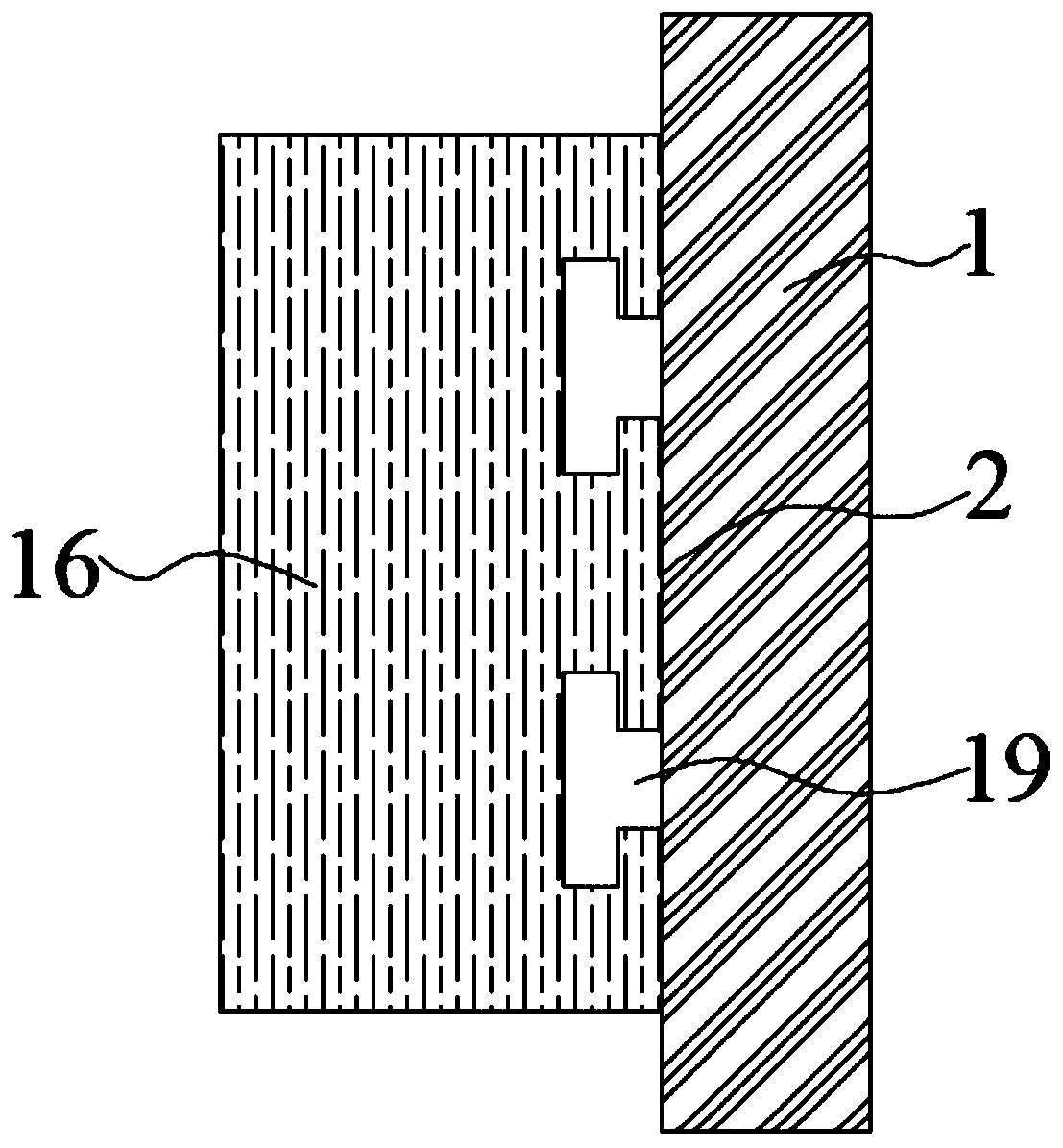
[0022] The following will combine Figure 1 ~ Figure 3 A stamping device for an electromechanical accessory according to an embodiment of the present invention is described in detail.

[0023] refer to Figure 1 ~ Figure 3 As shown, a stamping device for electromechanical accessories provided by the embodiment of the present invention includes a box body 1, a hydraulic machine A3 is installed inside the box body 1, and one end of a hyd...


PUM


Abstract

The invention discloses an electromechanical part stamping device, and belongs to the technical field of electromechanical part manufacturing. The electromechanical part stamping device includes a boxbody, a hydraulic machine A is installed inside the box body, one end of a hydraulic rod A is slidably connected to the outer wall of the bottom surface of the hydraulic machine A, the other end of the hydraulic rod A extends to the inside of a working groove and is fixedly connected to the upper surface of a pressure plate, and the outer wall of the bottom surface of the pressure plate is detachably connected to the upper surface of a mold plate A through bolts A. According to the electromechanical part stamping device, the pressure plate and the mold plate A can be detachably connected through the bolts A, a support plate and a mold plate B can be detachably connected through bolts B, and therefore the device can be suitable for a variety of mold plates in different sizes and can be used for stamping parts in various sizes, then a hydraulic machine B runs to drive a hydraulic rod B to stretch out and contract back so as to drive a transverse plate to move vertically, finished partscovering the inner wall of the bottom face of the mold plate B can be vertically moved out of the mold plate B, the finished parts can be quickly taken out, and the electromechanical part stamping device is suitable for being widely used and promoted.

Description

technical field [0001] The invention relates to a punching device, in particular to a punching device for electromechanical accessories. Background technique [0002] In the manufacturing process of electromechanical equipment, accessories need to be stamped and shaped, so a stamping device for electromechanical accessories is needed. [0003] Patent No. CN 201821298256.5 discloses an environmentally friendly stamping device for electromechanical accessories, which is convenient to move and suitable for stamping devices for electromechanical accessories used in the production and forging process of electromechanical accessories. [0004] Although the above-mentioned patented solution solves the shortcomings of the traditional electromechanical accessories stamping device, there are still some shortcomings in the solution. Poor; 2. The existing electromechanical parts stamping device is easy to absorb the finished parts on the inner wall of the mold after stamping, which tak...

Claims


Application Information

Patent Timeline
Patent Type & Authority Applications(China)
IPC IPC(8): B21D22/02B21D37/04B21D45/04B21D55/00
CPCB21D22/02B21D37/04B21D45/04B21D55/00
Inventor 周孟强
Owner HUBEI POLYTECHNIC UNIV
Why Eureka
Try Eureka