Inclined Bed Double Spindle CNC Lathe

A technology of CNC lathe and inclined bed, applied in the field of CNC machine tools, can solve problems such as insufficient lubrication of guide rails, low machining accuracy, and reduced parts accuracy.

Active Publication Date: 2021-01-01
CHONGQING HONGGANG CNC MACHINE TOOL
View PDF6 Cites 2 Cited by
  • Summary
  • Abstract
  • Description
  • Claims
  • Application Information

AI Technical Summary

Problems solved by technology

[0004] The present invention intends to provide a double-spindle CNC lathe with an inclined bed to solve the problems of reduced precision of parts and insufficient lubrication of guide rails due to the need for multiple clamping of parts
[0006] The working principle and beneficial effects of this scheme are: in this scheme, two spindle assemblies are set up, the first spindle assembly and the second spindle assembly, and the machining of both ends of the workpiece can be completed by clamping the workpiece at one time, which improves the processing efficiency and can effectively Avoid the problem of low machining accuracy of parts due to multiple clamping

Method used


Image

  • Inclined Bed Double Spindle CNC Lathe
  • Inclined Bed Double Spindle CNC Lathe
  • Inclined Bed Double Spindle CNC Lathe

Examples


Embodiment 1

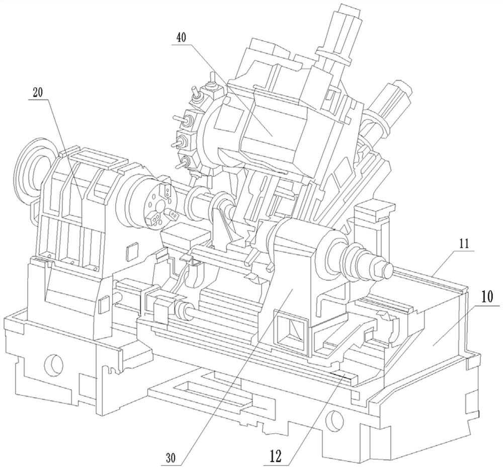
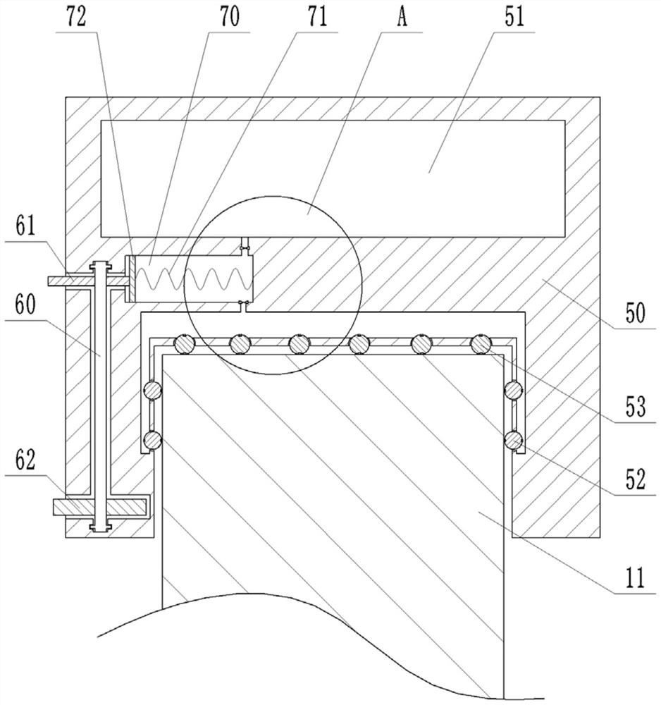
[0027] This embodiment is basically as figure 1 Shown: Slanted bed double-spindle CNC lathe, including hydraulic station, cooling system, protective cover and programmable control board, and the protective cover is equipped with a door that can be opened and closed. A slanted bed 10 is installed in the protective cover, and a first main shaft assembly 20, a second main shaft assembly 30 and a saddle assembly 40 are arranged on the slanted bed 10. The first main shaft assembly 20 is similar in structure to the second main shaft assembly 30, Both the first main shaft assembly 20 and the saddle assembly 40 are existing devices, and their specific structures will not be repeated here. Two saddle guide rails 11 and two second spindle guide rails 12 are also fixedly installed on the guide rail mounting surface of the inclined bed 10, and both the saddle guide rails 11 and the second spindle guide rails 12 are slidably connected with slide blocks 50, the saddle assembly 40 is slidab...

Embodiment 2

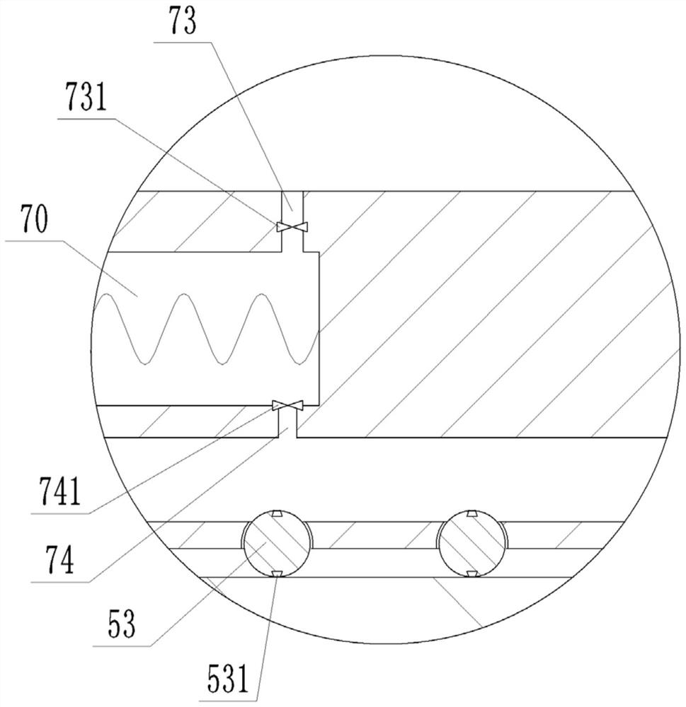
[0033] The difference between this embodiment and Embodiment 1 is that: Figure 4 As shown, in this implementation, an oiling layer is fixed at the oil outlet. In this embodiment, the oiling layer is a sponge layer 54, and the lubricating oil flowing out from the oil outlet cylinder 70 is applied on the surface of the saddle guide rail 11 through the sponge layer 54. .

Embodiment 3

[0035] The difference between this embodiment and Embodiment 1 is that: Figure 5 , Figure 6 As shown, the direction in which the oil outlet cylinder 70 is arranged and the specific structure of the power mechanism are different from the first embodiment. In this embodiment, the opening of the oil outlet cylinder 70 faces downward, and the piston 72 can slide up and down along the inner wall of the oil outlet cylinder 70 . The power mechanism comprises a threaded rod 80, a second gear 81 and a second rack meshed with the second gear 81, the threaded rod 80 is rotatably connected in the slide block 50, the second gear 81 is welded on the threaded rod 80, and the first rack Fixedly installed on the inclined bed 10, the length of the second rack can be reasonably set according to actual needs. The threaded rod 80 passes through the piston 72 and is threadedly connected with the piston 72; the stopper that restricts the rotation of the piston 72 is fixed in the oil outlet cylin...


PUM


Abstract

The invention belongs to the technical field of numerically controlled lathes, and particularly relates to a numerically controlled lathe with a slant lathe bed and double spindles. The numerically controlled lathe comprises a protective cover, wherein the slant lathe bed is arranged in the protective cover, and a first spindle assembly and a saddle assembly are arranged on the slant lathe bed; two saddle guide rails and two second spindle guide rails are arranged on a guide rail mounting surface of the slant lathe bed, sliders are connected onto the saddle guide rails and the second spindle guide rails in a sliding manner, and the saddle assembly is connected onto the saddle guide rails through the sliders; a second spindle assembly opposite to the first spindle assembly is connected ontothe second spindle guide rails through the sliders in a sliding manner; and an oil cavity, an oil outlet tube and a power mechanism are arranged in each slider, a piston is connected to inside of theoil outlet tube in a sliding manner, a channel is connected between the oil outlet tube and the oil cavity, a one-way oil inlet valve is arranged on the channel, a one-way oil draining valve is arranged on the oil outlet tube, and multiple oil outlets are formed in the lower part of the slider. According to the numerically controlled lathe in the scheme, machining of two ends of a workpiece can be completed by one-time clamping of the workpiece, and the machining efficiency can be improved.

Description

technical field [0001] The invention belongs to the technical field of numerical control machine tools, and in particular relates to a double-spindle numerical control lathe with an inclined bed. Background technique [0002] Slanted bed CNC lathe is a high-precision, high-efficiency automatic machine tool. Equipped with a multi-station turret or power turret, the machine tool has a wide range of technological performance, and can process complex workpieces such as straight cylinders, oblique cylinders, arcs, and various threads, grooves, and worms. Complement various compensation functions, and play a good economic effect in the mass production of complex parts. Slanted bed CNC lathes have the advantages of good stability, improved space utilization, and easy chip removal, and are currently widely used in various processing fields. [0003] Existing CNC lathes with inclined beds generally only have one main shaft assembly, and after the parts to be processed are clamped o...

Claims


Application Information

Patent Timeline
Patent Type & Authority Patents(China)
IPC IPC(8): B23B3/30B23B25/04B23Q1/01B23Q11/12
CPCB23B3/30B23B25/04B23Q1/015B23Q1/017B23Q11/12
Inventor 汪博强汪传宏汪洋王小玲饶贝宁
Owner CHONGQING HONGGANG CNC MACHINE TOOL
Why Eureka
Try Eureka