
Electric motor control device

a control device and motor technology, applied in the direction of programme control, multiple motor speed/torque control, multiple dynamo-electric motor speed regulation, etc., can solve the problems of degrading follow-up performance, affecting the performance of the motor, and affecting the operation of the motor, so as to prevent deterioration in machining accuracy, minimize the displacement of the movable component, and minimize the effect of thermal displacemen

Active Publication Date: 2016-04-19
OKUMA CORP
View PDF4 Cites 1 Cited by
  • Summary
  • Abstract
  • Description
  • Claims
  • Application Information

AI Technical Summary

Benefits of technology

The present invention is a control device for an electric motor that minimizes displacement of a movable component caused by the preload torque. It uses a torque arbitration controller and a preload controller that adjusts the torque command for the auxiliary electric motor based on the time elapsed since application or removal of the preload torque. This helps to reduce the heat generated and the risk of damage to the motor, while also preventing overload alarms and maintaining machining accuracy.

Problems solved by technology

However, the technique of applying a preload torque to two motors disclosed in JP 2010-172054 A cannot be applied to the tandem control electric motor control device having the torque arbitrator disclosed in JP 2003-079180 A because, if applied, as illustrated in FIG. 7, a torque arbitration value is generated when a preload torque is applied or removed, and displacement of the movable component occurs.
As a result, when a power transmission mechanism, such as a reduction gear or a gear, of a machine has large backlash or torsional moment, because an increase in gains of speed and position control loops oscillates electric motors and causes vibrations or unusual noise, gain should be lowered, which degrades follow-up performance.
As a result, greater thermal displacement shifts the center of the shaft, resulting in deterioration in machining accuracy, or the machine is stopped in response to an overload alarm for protecting the electric motors, resulting in decreased machining efficiency.
Although the problems can be solved by water cooling the electric motors or the machine as a method for minimizing such thermal displacement caused by heat generation, this approach increases the costs.
Further, although the problems can be solved by employing electric motors having greater continuous rated power as a method for minimizing heat generation of the electric motors, the increase in capacity of the electric motors increases the costs, and because the volume of the electric motors is increased, this approach upsizes the machine and reduces the design flexibility of the machine.

Method used


Image

  • Electric motor control device
  • Electric motor control device
  • Electric motor control device

Examples


Embodiment Construction

[0027]An embodiment of the present invention will be described below with reference to the drawings. Elements, signals, or others denoted by the same reference symbols or numerals have the same function and the same performance unless specifically indicated otherwise.

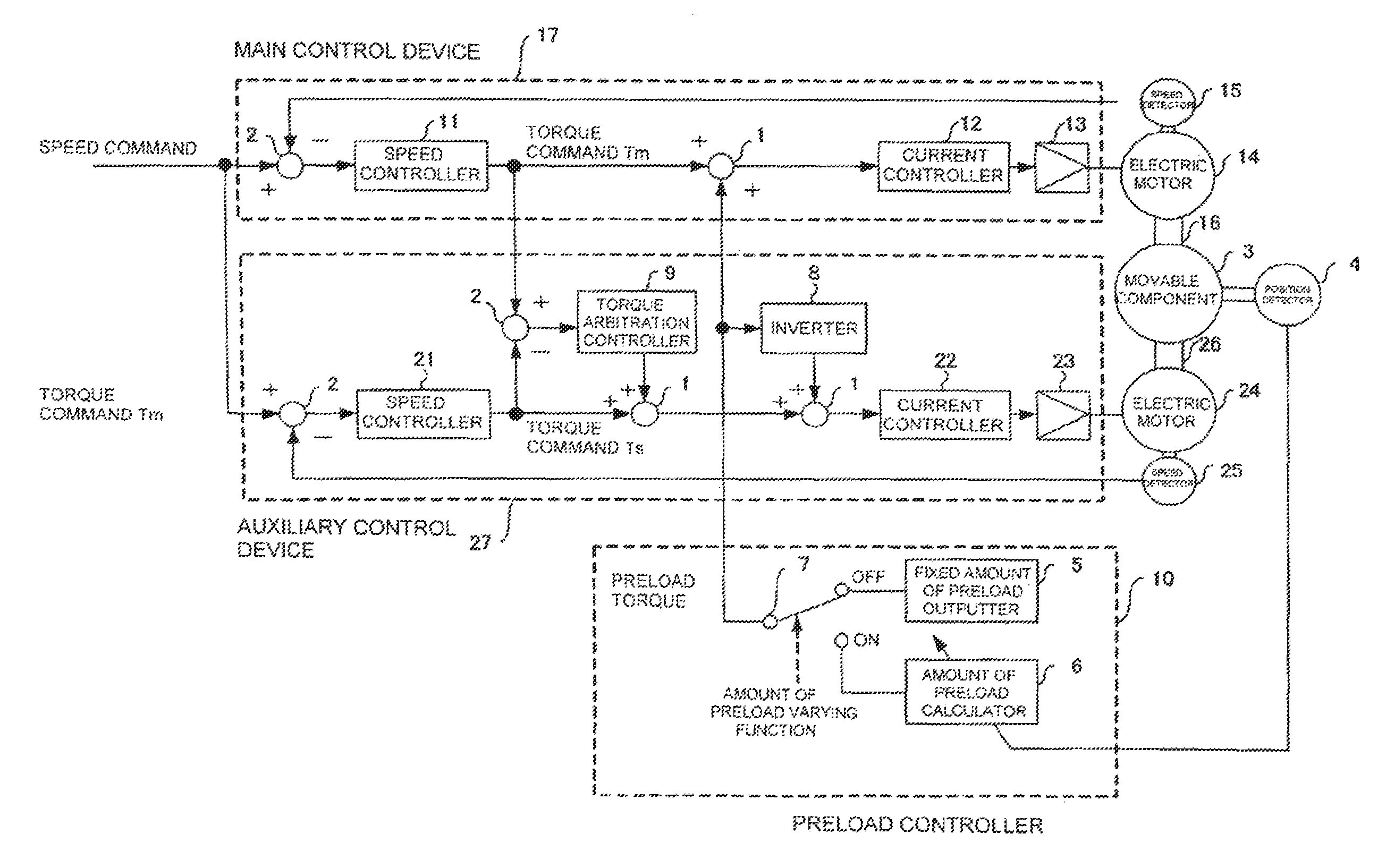
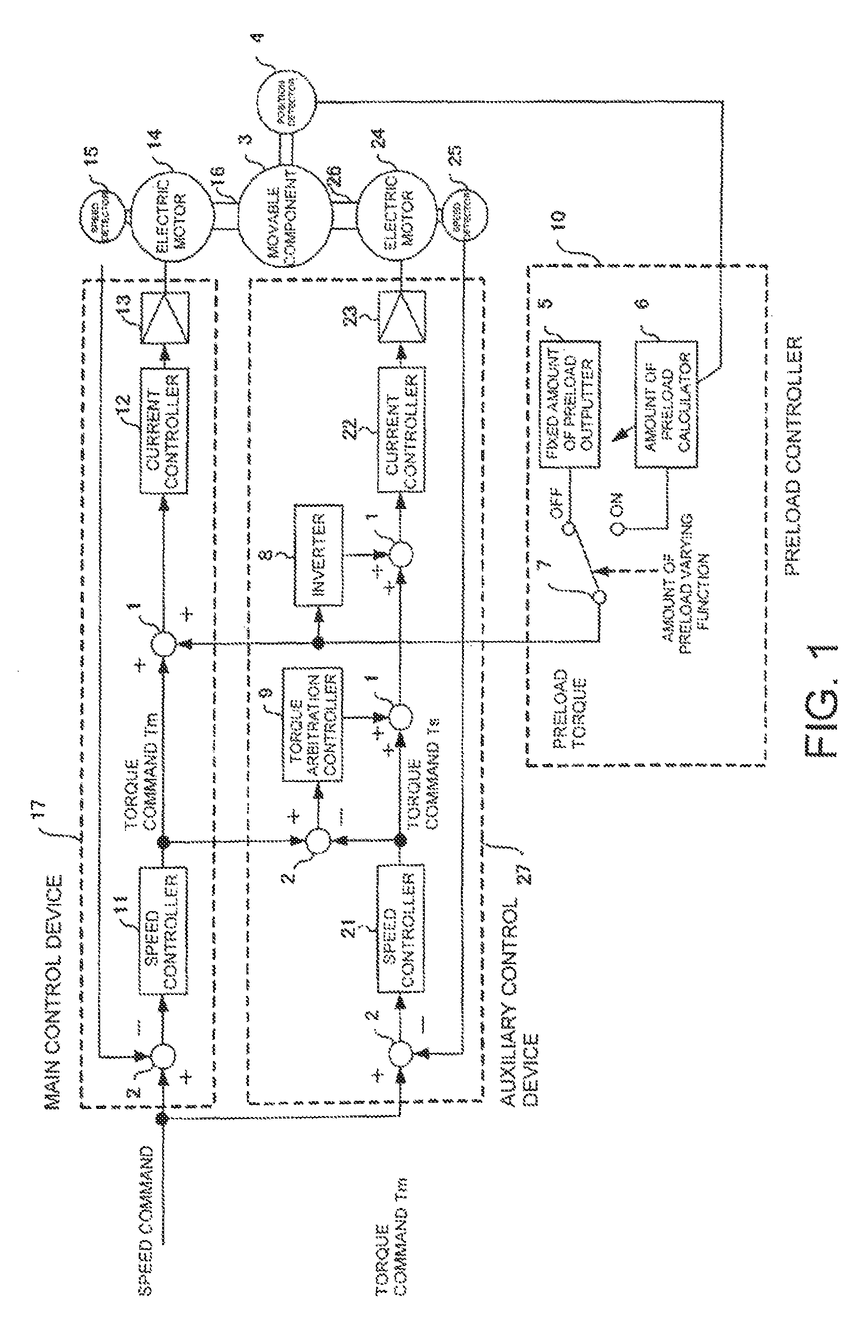
[0028]FIG. 1 is a block diagram of a control system for a tandem control electric motor control device having a torque arbitration controller and a preload controller for applying a preload torque according to an embodiment of the present invention. Description of components corresponding to those of the related art is not repeated here.

[0029]Referring to FIG. 1, a preload controller 10 includes an amount of preload calculator 6 for calculating and outputting an amount of preload based on positional information detected by a position detector 4, and a fixed amount of preload outputter 5 for outputting a fixed amount of preload. The preload controller 10 has the function of determining whether an amount of preload varyin...


PUM


Abstract

An electric motor control device for performing tandem control for driving one movable component includes, for each electric motor, a position controller, a speed controller, and a current controller. Further, each electric motor also has a preload controller for adding a preload torque to a torque command Tm calculated by the speed controller, and to a torque command Ts calculated by the speed controller. The preload controller calculates a minimum necessary preload torque for eliminating backlash in accordance with a position of the movable component.

Description

CROSS-REFERENCE TO RELATED APPLICATIONS[0001]This application claims priority under 35 U.S.C. §119(a)-(d) to Japanese Patent Application No. 2013-083697, filed Apr. 12, 2013, the content of which is incorporated herein by reference in its entirety as part of the present disclosure.FIELD OF THE INVENTION[0002]The present invention relates to a control device for driving in tandem a plurality of electric motors for use in, for example, a machine tool, and in particular, relates to a control method for eliminating factors causing instability in control that come from a power transmission mechanism typically including a belt or a gear between an electric motor and a control target by performing compensation with micro torques having different polarities on torque command values that are to be applied to the electric motors. Also, the present invention relates to control for causing a current that is to be applied to an electric motor to vary in accordance with the attitude of a machine....

Claims


Application Information

Patent Timeline
Patent Type & Authority Patents(United States)
IPC IPC(8): G05B11/32G05B19/404H02P5/52H02P5/54H02P6/04
CPCG05B19/404G05B2219/37297G05B2219/41034G05B2219/41264G05B2219/41265G05B2219/41395
Inventor SAKAI, TAKESHISATAKE, AKIYOSHI
Owner OKUMA CORP
Learn More