Photovoltaic array arrangement method and photovoltaic array arrangement scheme automatic generation system

A photovoltaic array and photovoltaic system technology, applied in the direction of instruments, data processing applications, design optimization/simulation, etc., can solve the problem of single scene, failure to reach system installation capacity, system annual power generation arrangement results, failure to deal with irregular installation areas, Problems such as multiple obstacles and shadows in multiple installation areas

Pending Publication Date: 2020-02-28
SHANGHAI ELECTRIC DISTRIBUTED ENERGY TECH CO LTD
View PDF7 Cites 10 Cited by
  • Summary
  • Abstract
  • Description
  • Claims
  • Application Information

AI Technical Summary

Problems solved by technology

Usually, the layout design of photovoltaic arrays is mainly completed by professionals based on experience or with the aid of auxiliary software. The key factors such as the arrangement, inclination, orientation, and spacing of photovoltaic modules are mostly empirical parameters, which cannot achieve the maximum installed capacity of the system or the system annual capacity. The layout result with the largest power generation; in addition, the existing optimized layout technology scheme considers a single scenario, and cannot deal with complex situations such as irregular installation areas, multiple installation areas, multiple obstacles, and shadows

Method used


Image

  • Photovoltaic array arrangement method and photovoltaic array arrangement scheme automatic generation system
  • Photovoltaic array arrangement method and photovoltaic array arrangement scheme automatic generation system
  • Photovoltaic array arrangement method and photovoltaic array arrangement scheme automatic generation system

Examples


Embodiment 1

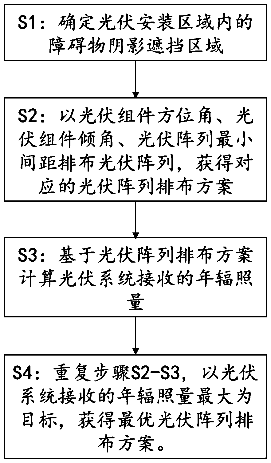
[0093]Embodiment 1 provides a photovoltaic array arrangement method, wherein the photovoltaic array includes at least one photovoltaic module, and the photovoltaic modules are arranged according to the installation azimuth angle of the photovoltaic module and the installation inclination angle of the photovoltaic module, and the distance between adjacent photovoltaic arrays is at least one photovoltaic array The spacing is arranged in parallel. Such as figure 1 As shown, the photovoltaic array arrangement method includes the following steps:

[0094] S1: Determine the shadowed area of ​​obstacles in the photovoltaic installation area, and take the area outside the shadowed area of ​​obstacles in the photovoltaic installation area as the actual installable area;

[0095] S2: In the actual installable area, arrange the photovoltaic arrays according to the azimuth angle of the photovoltaic modules, the inclination angle of the photovoltaic modules, and the minimum spacing of the...

Embodiment 2

[0101] Embodiment 2 provides a photovoltaic array arrangement method, wherein the photovoltaic array includes at least one photovoltaic module, and the photovoltaic modules are arranged according to the installation azimuth angle of the photovoltaic module and the installation inclination angle of the photovoltaic module, and the distance between adjacent photovoltaic arrays is at least one photovoltaic array The spacing is arranged in parallel. The photovoltaic array arrangement method includes the following steps:

[0102] S1: Determine the shadowed area of ​​obstacles in the photovoltaic installation area, and use the area outside the shadowed area of ​​obstacles in the photovoltaic installation area as the actual installable area.

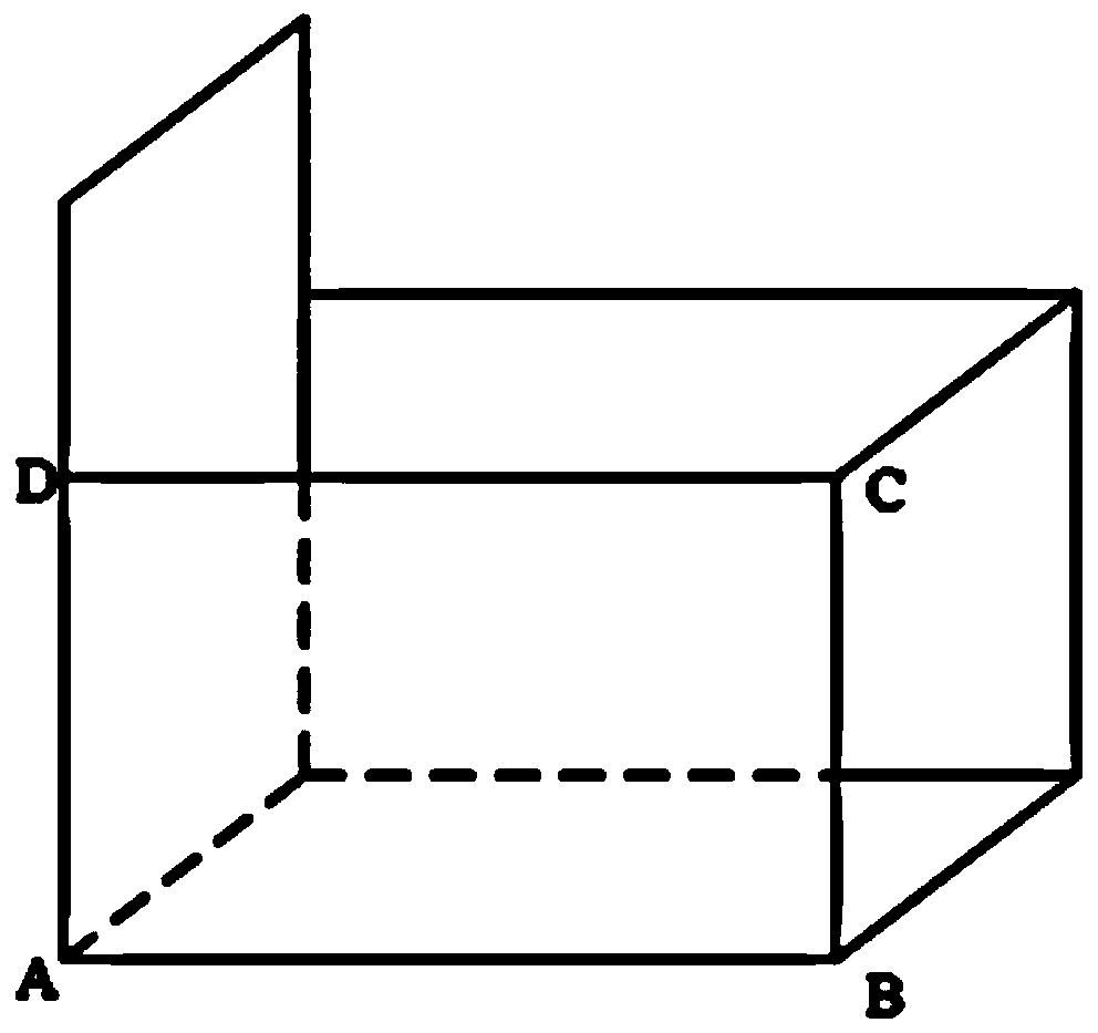
[0103] There are many types of obstacles and different shapes. In order to unify and simplify the obstacle model, all obstacles are equivalent to a three-dimensional figure composed of multiple vertical rectangular surfaces, and the height of e...

Embodiment 3

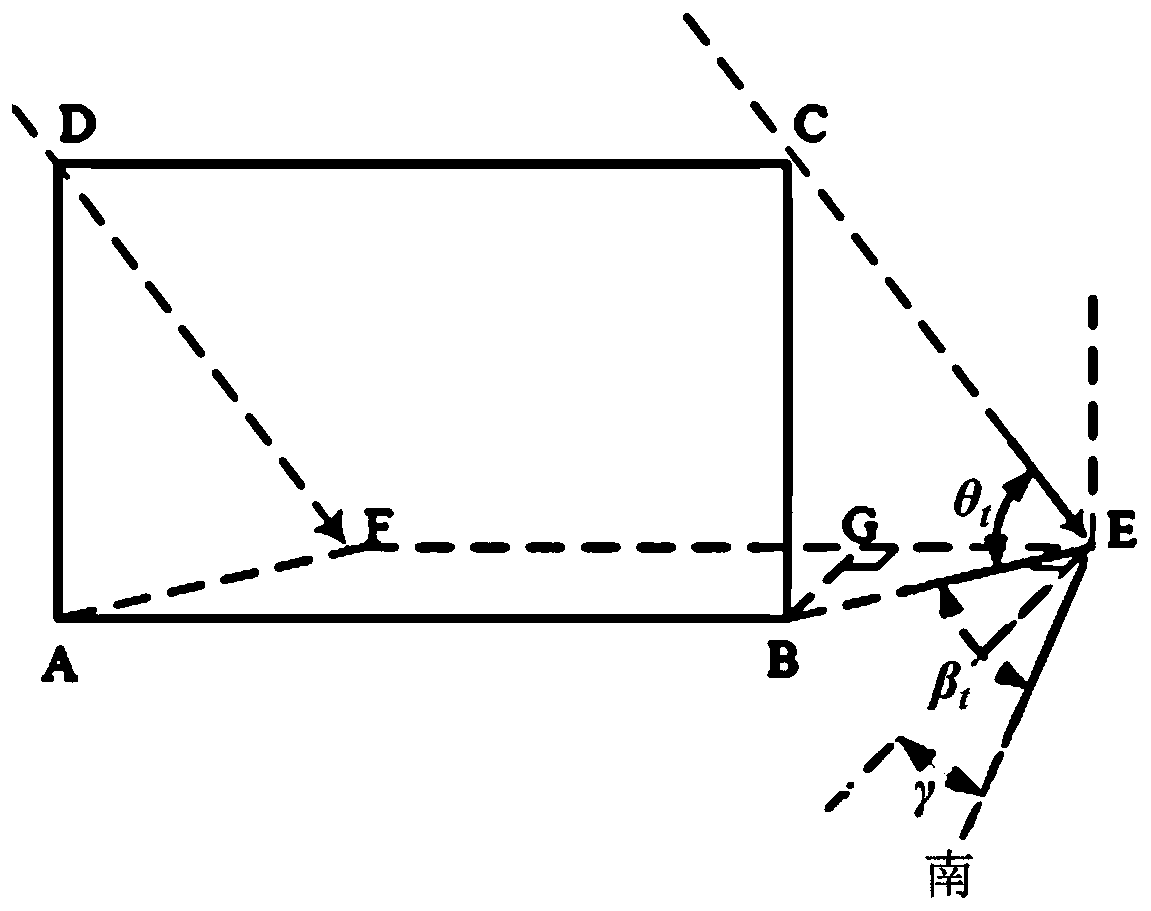
[0150] Embodiment 3 discloses a photovoltaic array arrangement method. Compared with Embodiment 2, in Embodiment 3, after 1-4 photovoltaic modules are arranged side by side to form a photovoltaic module group, the photovoltaic array is arranged, such as Figure 12 shown. Suppose the coordinates of point A are (x, y), then the coordinates of point B are (x+w cosγ, y-w sinγ), and the coordinates of point C are (x+w cosγ+l sinγ, y-w sinγ+l cosγ ), the coordinates of point D are (x+l sinγ, y+l cosγ), the coordinates of point E are (x, y)+n (w cosγ, -w sinγ), and the coordinates of point F are (x+ l·sinγ,y+l·cosγ)+n·(w·cosγ,-w·sinγ). In the formula, l is the length of the photovoltaic module, w is the width of the photovoltaic module, and γ is the installation azimuth of the photovoltaic module.

[0151] Further, the above-mentioned steps S2-S4 are carried out for photovoltaic module groups with different numbers of parallel rows, and the corresponding photovoltaic array arrangem...


PUM


Abstract

The invention discloses a photovoltaic array arrangement method and a photovoltaic array arrangement scheme automatic generation system, and the method comprises the steps: S1, determining an obstacleshadow shielding region in a photovoltaic installation region, and enabling a region, except the obstacle shadow shielding region, in the photovoltaic installation region to serve as an actual installable region; S2, in the actual installable area, arranging photovoltaic arrays according to the azimuth angles of the photovoltaic assemblies, the inclination angles of the photovoltaic assemblies and the minimum intervals of the photovoltaic arrays, and obtaining a corresponding photovoltaic array arrangement scheme; S3, calculating annual irradiation received by the photovoltaic system based onthe photovoltaic array arrangement scheme; and S4, repeating the steps S2-S3, taking the maximum annual irradiation received by the photovoltaic system as a target, obtaining an optimal photovoltaicarray arrangement scheme, and completing photovoltaic array arrangement. According to the method, the arrangement of the photovoltaic arrays in the irregular installation area can be optimally designed, and meanwhile, the influence of barrier shadows is considered.

Description

technical field [0001] The invention belongs to the technical field of photovoltaic power station construction, and relates to a photovoltaic array arrangement method and a photovoltaic array arrangement scheme automatic generation system. Background technique [0002] In the design of photovoltaic systems, the arrangement and arrangement of photovoltaic arrays are very important for accurately evaluating the installed capacity and power generation of photovoltaic systems. A reasonable arrangement scheme can not only increase the installed capacity of the system, reduce the loss of power generation caused by shading, but also provide an intuitive reference for on-site construction. [0003] The key factors to be considered in the photovoltaic array arrangement plan are photovoltaic module orientation, inclination angle, front and rear installation distance, installation method (horizontal multiple / single row, vertical multiple / single row), obstacles and their shadows, etc. ...

Claims


Application Information

Patent Timeline
IPC IPC(8): G06F30/20G06Q50/06
CPCG06Q50/06
Inventor 李路遥李元浩古云蛟杨青马玉鑫葛兴凯常悦曹超张弛
Owner SHANGHAI ELECTRIC DISTRIBUTED ENERGY TECH CO LTD
Why Eureka
Try Eureka