A portable proximity switch testing device
A technology for proximity switches and test equipment, applied in the direction of instruments, etc., can solve the problems of slow detection speed, time-consuming and laborious detection, etc., to achieve the effect of contrast and avoid time waste
- Summary
- Abstract
- Description
- Claims
- Application Information
AI Technical Summary
Problems solved by technology
Method used
Image
Examples
Embodiment 1
[0027] A portable proximity switch test device such as Figure 1-3 As shown, it includes a mounting housing 1, a handle 2, a connection box 5, a first bearing seat 6, a first rotating rod 7, a mounting rod 9, a conversion device 10 containing metal for detection, and a socket 12, specifically:
[0028] A handle 2 is provided on the lower side of the mounting shell 1 , a first empty slot 3 is opened on the right part of the mounting shell 1 , and side holes 4 are opened on the front and rear sides of the right part of the mounting shell 1 . The hole 4 is communicated with the first empty groove 3 , the left part of the installation casing 1 is connected with a connection box 5 at the front and rear sides, and the position of the installation casing 1 in the connection box 5 is connected with a first bearing. The seat 6, the first bearing seat 6 is connected with a first rotating rod 7, the right side of the connecting box 5 is provided with a through hole 8, and the first rotat...
Embodiment 2
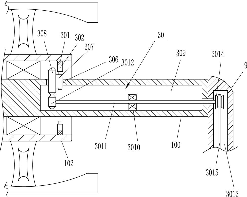
[0033] On the basis of Example 1, as Figure 2-3 As shown, the conversion device 10 includes a fixed rod 100, a second bearing seat 101, a rotating ring 102, a connecting block 103, a metal sheet 104 and a rotating handle 105, and the mounting rod 9 is connected with the fixed rod 100, so The middle of the fixing rod 100 is provided with a second bearing seat 101, specifically:
[0034] The outer side of the second bearing seat 101 is provided with a rotating ring 102, the outer side of the rotating ring 102 is provided with a connecting block 103, the outer side of the connecting block 103 is connected with a metal sheet 104, and the outer side of the rotating ring 102 is provided with multiple sets of rotating put 105.
[0035] During the specific operation of the above embodiment, when the proximity switch is detected, the rotating ring 102 can be rotated by the rotating handle 105, and the rotating ring 102 will drive the connecting block 103 and the metal sheet 104 to pe...
Embodiment 3
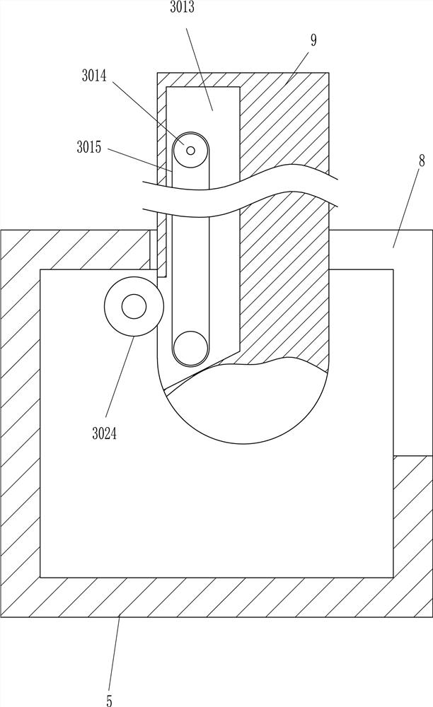
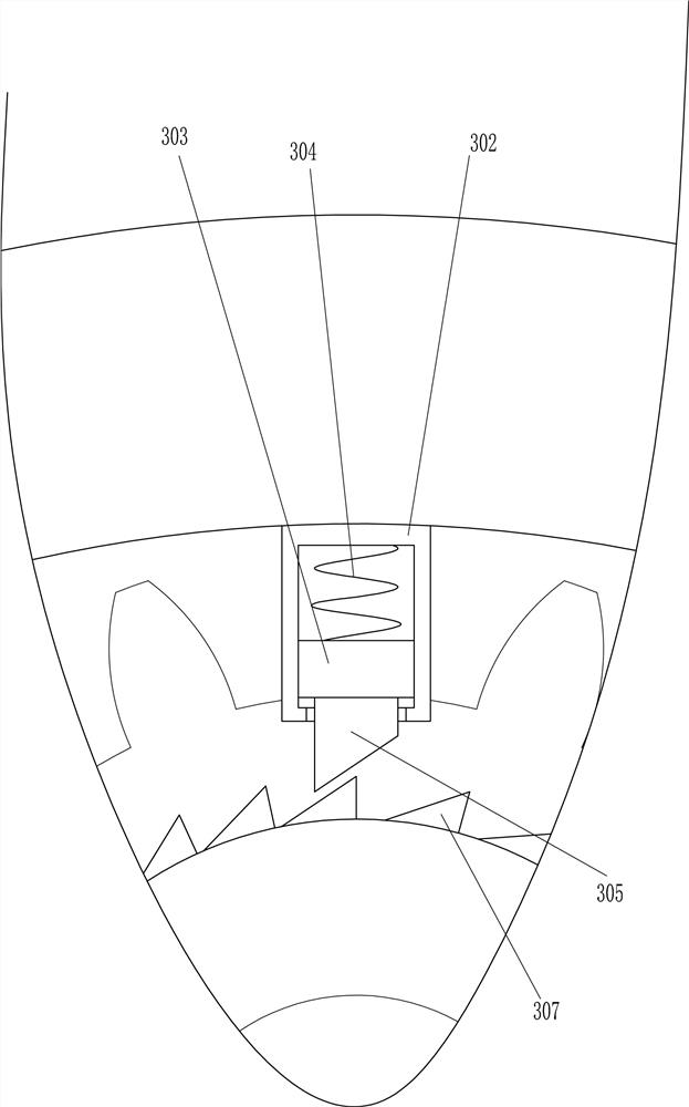
[0038] On the basis of Example 2, as Figure 4-8 As shown, it also includes a follower device 30 that can make the proximity switch linked with the conversion device 10 , and the follower device 30 includes a mounting ring 301 , a sliding rail 302 , a sliding block 303 , an elastic member 304 , and a pawl 305 , the first rotating shaft 306, the ratchet 307, the first gear 308, the third bearing seat 3010, the second rotating rod 3011, the second gear 3012, the first pulley 3014, the toothed belt 3015, the guide rail 3016, the guide sleeve 3017, the moving rod 3018 , the second rotating shaft 3019, the second pulley 3020, the fourth bearing seat 3021, the flat belt 3022, the third rotating rod 3023 and the third gear 3024, specifically:
[0039] The follower device 30 is arranged on the rear side mounting rod 9 and is connected to the conversion device 10 and to the socket 12 . A mounting ring 301 is connected to the right side of the rotating ring 102 . A plurality of sets of...
PUM
 Abstract
Description
Claims
Application Information
 - R&D
- Intellectual Property
- Life Sciences
- Materials
- Tech Scout
- Unparalleled Data Quality
- Higher Quality Content
- 60% Fewer Hallucinations
Browse by: Latest US Patents, China's latest patents, Technical Efficacy Thesaurus, Application Domain, Technology Topic, Popular Technical Reports.
© 2025 PatSnap. All rights reserved.Legal|Privacy policy|Modern Slavery Act Transparency Statement|Sitemap|About US| Contact US: help@patsnap.com


