Highway bridge expansion joint monitoring connection device

A technology for road bridges and connecting devices, which is applied in the field of expansion joint devices, can solve the problems of affecting driving comfort, prone to damage, subsidence, wrong platform, safety accidents, etc., and achieve the effect of avoiding road bumps

Active Publication Date: 2020-06-12
王俊华
View PDF5 Cites 0 Cited by
  • Summary
  • Abstract
  • Description
  • Claims
  • Application Information

AI Technical Summary

Problems solved by technology

In order to adjust the displacement and connection between the superstructure of the bridge, expansion joints need to be installed, but if the expansion joints are not properly set up, the expansion joints of the bridge are prone to damage, sinking, and misalignment, which will cause jumping impact on the bridge when vehicles pass by , generate additional load, affect driving comfort, and cause safety accidents in severe cases

Method used


Image

  • Highway bridge expansion joint monitoring connection device
  • Highway bridge expansion joint monitoring connection device
  • Highway bridge expansion joint monitoring connection device

Examples


Embodiment Construction

[0032] The present invention will be described in detail below in conjunction with the accompanying drawings, so that those of ordinary skill in the art can implement it after referring to this specification.

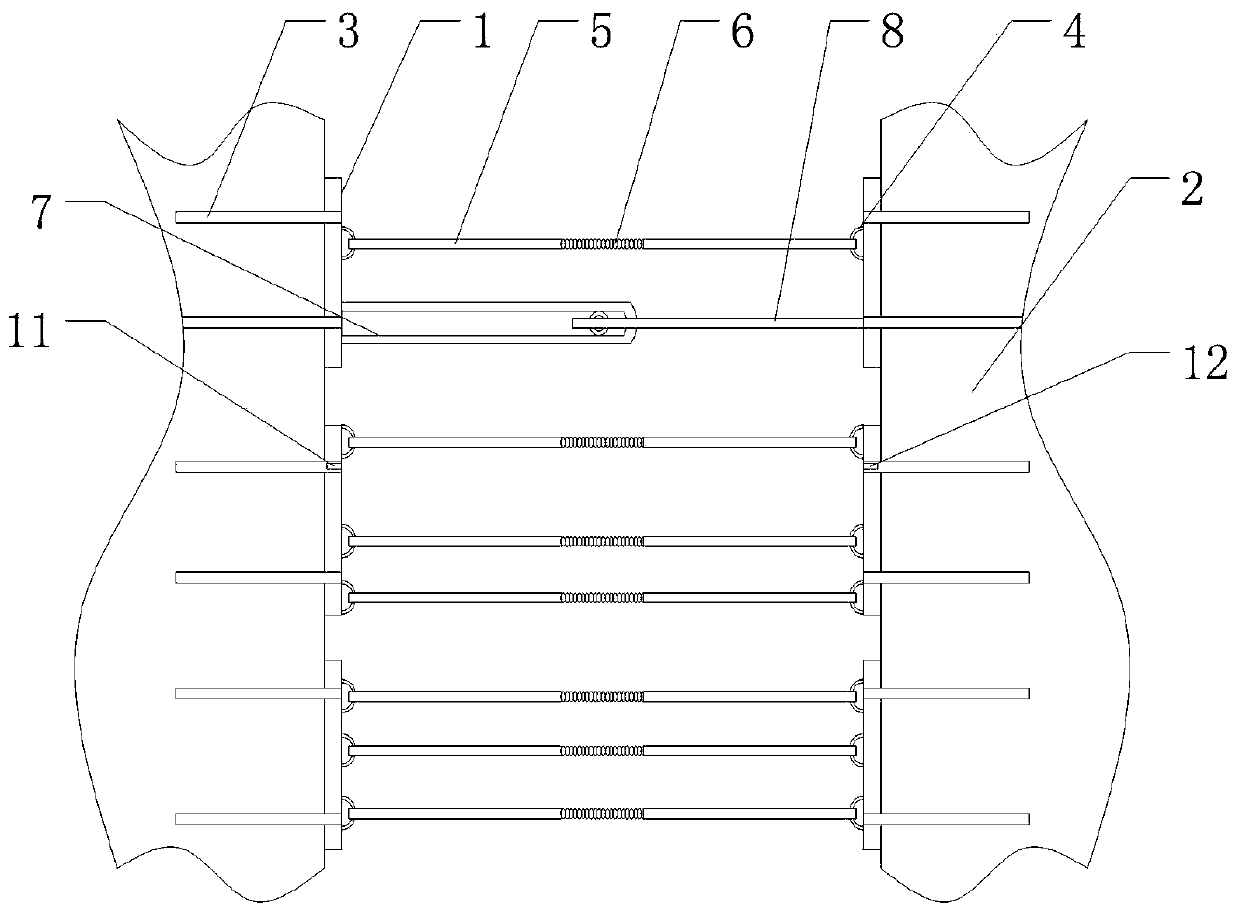
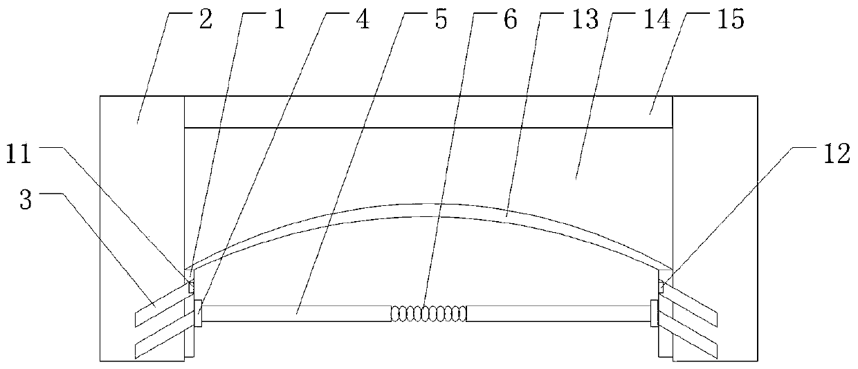
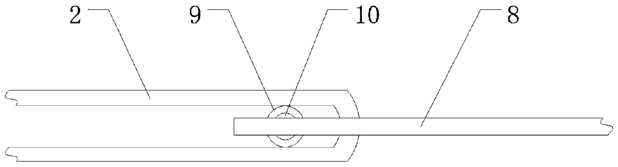
[0033] Such as Figure 1-Figure 3 As shown, a highway bridge expansion joint monitoring connection device includes: a connecting rod 1, which is horizontally anchored on the two side walls of the expansion joint 2 along the width direction of the road or bridge, and the connection on the two side walls The rods 1 are symmetrically arranged; through holes are evenly spaced along the length extension direction of the connecting rod 1; the connecting rod 1 passes through the through holes and the anchor rod 3 extending into the side wall and the expansion joint 2 fixed connection; the opposite surface of the connecting rod 1 on the two side walls is symmetrically provided with a connecting ring 4;

[0034] A connecting beam, which includes a connecting rib 5 and a connect...


PUM


Abstract

The invention discloses a highway bridge expansion joint monitoring and connecting device. The highway bridge expansion joint monitoring and connecting device comprises connecting rods, connecting beams, a transverse monitoring portion, a longitudinal monitoring portion and a buffering portion, wherein the connecting rods are anchored to the side walls of an expansion joint by means of anchor rods; connecting rings are arranged on the connecting rods; one end of a connecting rib, forming each connecting beam, is connected to the corresponding connecting ring, and the other end is connected with a connecting spring; the transverse monitoring portion comprises a first supporting rib, a second supporting rib and a monitoring ball; the first supporting rib and the second supporting rib are nested with each other and connected to the surfaces of the connecting rods, and a pressure sensor is arranged in the monitoring ball; the monitoring ball is arranged between the first supporting rib andthe second supporting rib; an infrared receiver and an emitter which form the longitudinal monitoring portion are respectively arranged at the end parts of the anchor rods; arc-shaped supporting plates forming the buffering portion are arranged on the connecting rods; a rubber cushion layer is arranged on the arc-shaped supporting plates; and a cover plate is buckled on the expansion joint. Whilenormal expansion and contraction of the expansion joint are met, the highway bridge expansion joint monitoring and connecting device can realize real-time monitoring of transverse and longitudinal displacement of the expansion joint, and then take measures conveniently in time when a road or a bridge is damaged, so as to guarantee formation safety.

Description

technical field [0001] The invention relates to the technical field of expansion joint devices, in particular to a monitoring and connection device for expansion joints of highway bridges. Background technique [0002] Expansion joints refer to the expansion joints set between the ends of the two girders, between the ends of the girder and the abutment, or at the hinge position of the bridge, as well as in the transverse direction of the road surface, in order to meet the deformation requirements of the bridge deck or road surface. It is required that the expansion joints can freely expand and contract in two directions parallel to and perpendicular to the bridge axis, and are firm and reliable. The vehicles should run smoothly without sudden jumps and noises; they should be able to prevent rainwater and garbage from infiltrating and blocking; installation, inspection, and maintenance , Elimination of dirt should be simple and convenient. [0003] The role of expansion join...

Claims


Application Information

Patent Timeline
Patent Type & Authority Patents(China)
IPC IPC(8): G01B5/02G01B5/14G01B5/30G01B11/02G01B11/14G01B11/16E01D19/06
CPCE01D19/06G01B5/02G01B5/14G01B5/30G01B11/02G01B11/14G01B11/16
Inventor 王俊华李智强夏云飞严贺超许彩缤李盟冯军亮李新辉郑国金董斌
Owner 王俊华
Why Eureka
Try Eureka