Electromechanical brake and actuator thereof
An electromechanical brake and actuator technology, applied in the direction of brakes, brake actuators, brake components, etc., can solve the problems of reducing the reliability of electrical connections, not giving solutions, increasing the difficulty of assembly, etc., to achieve The effect of reducing assembly time and cost, reducing the difficulty of replacement, and reducing the space occupied by the vehicle
- Summary
- Abstract
- Description
- Claims
- Application Information
AI Technical Summary
Problems solved by technology
Method used
Image
Examples
Embodiment 1
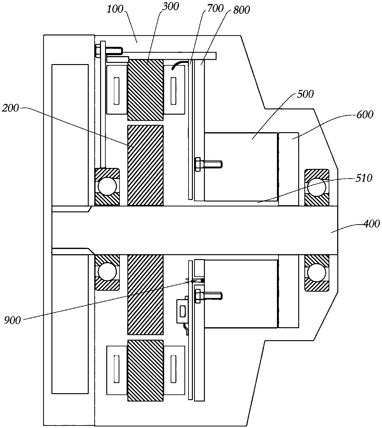
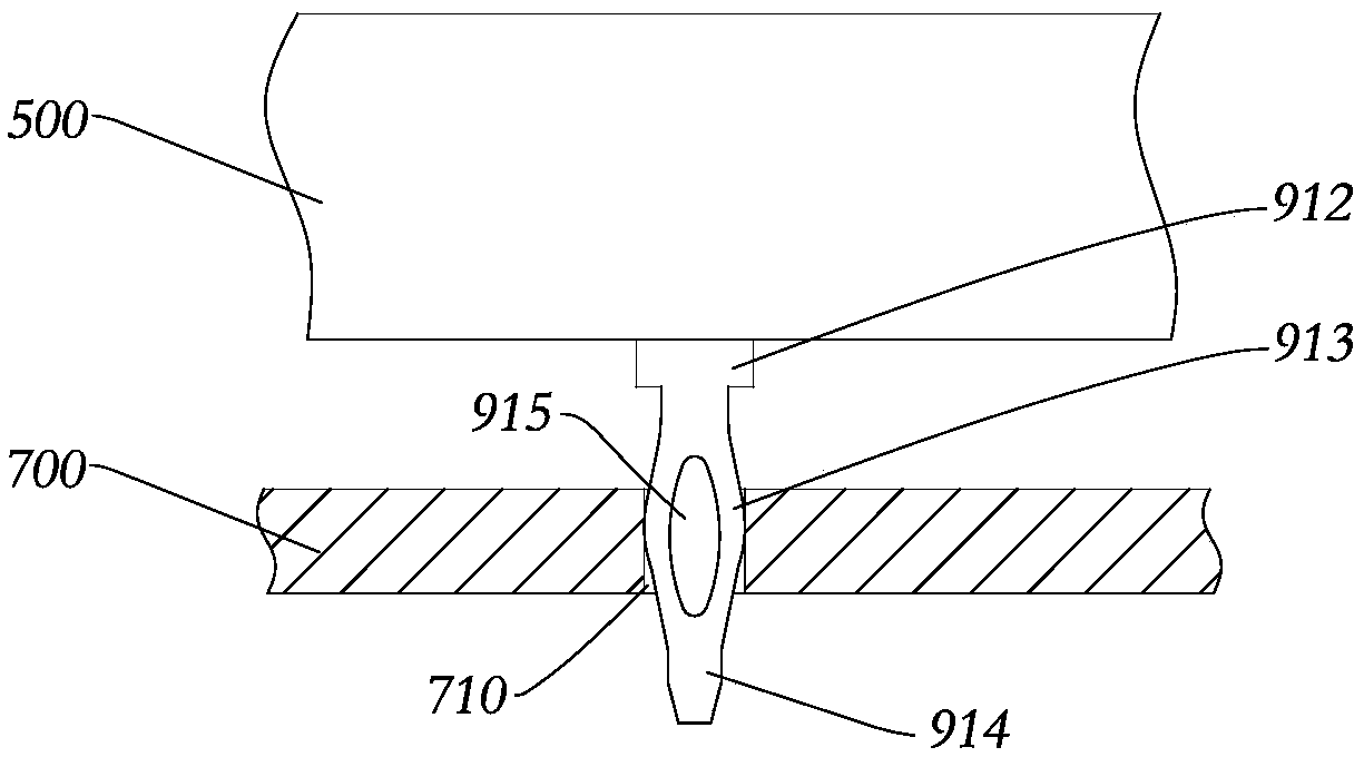
[0071] refer to figure 1 , 2 , the actuator of the electromechanical brake proposed in Embodiment 1 of the present invention includes: a housing 100; and a motor housed in the housing 100, the motor includes a motor shaft 400; The clutch, the electromagnetic clutch is used to lock or release the motor shaft 400 ; and the circuit board 700 housed in the housing 100 ; and the electrical connector 900 is used to establish an electrical connection between the electromagnetic clutch and the circuit board 700 . Wherein, the motor includes a motor shaft 400, a motor stator 300 and a motor rotor 200. The motor rotor 200 is fixedly connected to the motor shaft 400. When the motor rotor 200 rotates relative to the motor stator 300, it can synchronously drive the motor shaft 400 to rotate to realize braking torque output. Although an inner rotor motor is used in this embodiment for illustration, it is not limited thereto, and the motor of the actuator can be any type of motor that uses ...
Embodiment 2
[0078] refer to Figure 4 , 5 The difference between this embodiment and Embodiment 1 is that the electrical connector 900 includes a male connector 920 disposed on the circuit board 700 and a female connector 930 disposed on the stator 500 that are plugged and connected to each other. Said: the electrical connector 900 is a male connector 920 and a female connector 930 designed in pairs, the male connector 920 is installed on the circuit board 700, and the female connector 930 is installed on the stator 500. When assembling, the male end connector 920 and the female end connector 930 are mated with each other to establish an electrical connection between the electromagnetic clutch and the circuit board 700, since the male end connector 920 and the female end connector 930 are matched in pairs design, the reliability of the connection between the two is basically not affected by the structure of the electromagnetic clutch and the circuit board 700 itself.
[0079] refer to ...
Embodiment 3
[0083] refer to Figure 7 , the difference between this embodiment and Embodiment 1 is that: the male connector 920 and the female connector 930 respectively have insertion holes and pins, that is, the male connector 920 is provided with pins 922, and the female connector 930 Insertion holes 932 are provided, such as split slot type insertion holes, wire spring insertion holes, crown spring insertion holes (insert holes with built-in multiple elastic reeds), etc., and the pins 922 are inserted into the insertion holes 932 . During assembly, the operator can observe the relative position of the insertion hole 932 and the pin 922 and align the two for insertion, which reduces the difficulty of assembly. After the assembly is completed, the pin 922 is not exposed, which has a good effect on the pin 922 Protect. As an equivalent variation of this embodiment, the male connector is provided with an insertion hole, the female connector is provided with a pin, and the pin is inserted...
PUM
 Abstract
Description
Claims
Application Information
 - R&D
- Intellectual Property
- Life Sciences
- Materials
- Tech Scout
- Unparalleled Data Quality
- Higher Quality Content
- 60% Fewer Hallucinations
Browse by: Latest US Patents, China's latest patents, Technical Efficacy Thesaurus, Application Domain, Technology Topic, Popular Technical Reports.
© 2025 PatSnap. All rights reserved.Legal|Privacy policy|Modern Slavery Act Transparency Statement|Sitemap|About US| Contact US: help@patsnap.com


