
Convenient bionic massage instrument structure

A portable, bionic technology, applied in vibration massage, massage auxiliary products, physical therapy and other directions, can solve the problems of inability to relieve pain, promote blood circulation and remove blood stasis, the massage intensity is difficult to achieve the expected effect, and the massage head movement frequency is low. Improve active use experience, obvious noise and vibration, and small size

Pending Publication Date: 2020-02-28
深圳市康瑞普斯医疗器械有限公司
View PDF0 Cites 1 Cited by
  • Summary
  • Abstract
  • Description
  • Claims
  • Application Information

AI Technical Summary

Problems solved by technology

The eccentric wheel vibration type power transmission system achieves the effect of massage and maintenance by causing the vibration of the massage head through the high-speed rotation of the eccentric wheel. However, because this design uses the overall vibration as the output, the noise and vibration of the whole machine are relatively large, and the user experience is poor. In addition, the long-term high-frequency vibration also has a great impact on the strength of the product parts themselves, but because of the strong force of this type of massage head, many portable massagers still use this design; most of the planar reciprocating mechanism products use double heads or four heads Massage head, this solution is relatively stable compared with the eccentric wheel vibration solution, and the noise is also reduced, but the movement frequency of the massage head in the horizontal or vertical plane is low, and the massage force is difficult to achieve the expected effect, and it cannot relieve pain and promote blood circulation. Anticipated effects such as removing blood stasis

Method used


Image

  • Convenient bionic massage instrument structure
  • Convenient bionic massage instrument structure
  • Convenient bionic massage instrument structure

Examples


Embodiment Construction

[0027] The present invention will be further described below in conjunction with the accompanying drawings.

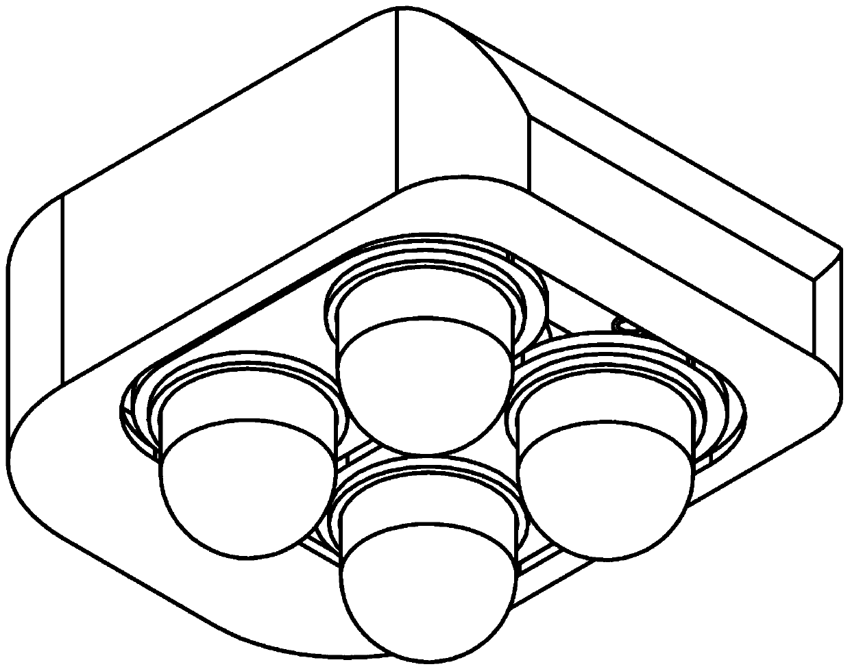
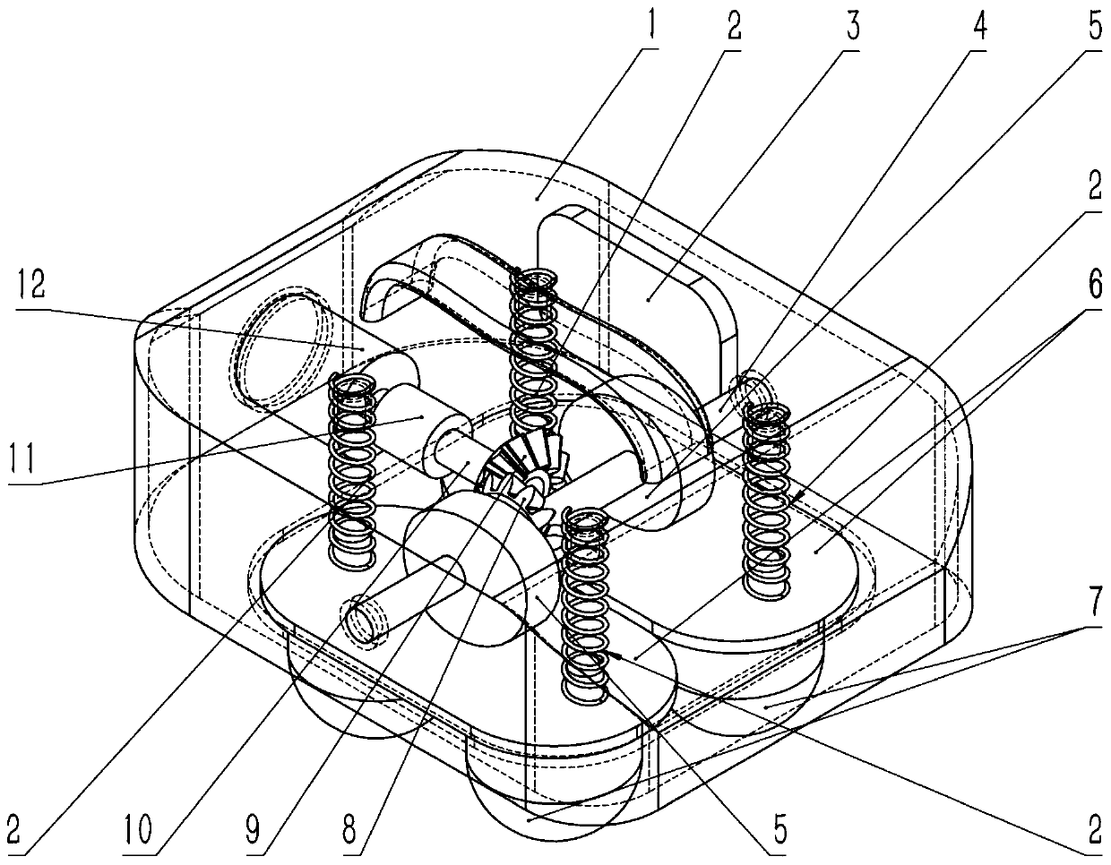
[0028] A portable bionic massager structure, including a shell 1, a return spring 2, a battery 3, a camshaft 4, a cam 5, a massage head base 6, a massage head 7, a driven gear 8, a driving gear 9, a gear shaft 10, and a shaft coupling Device 11, motor 12.

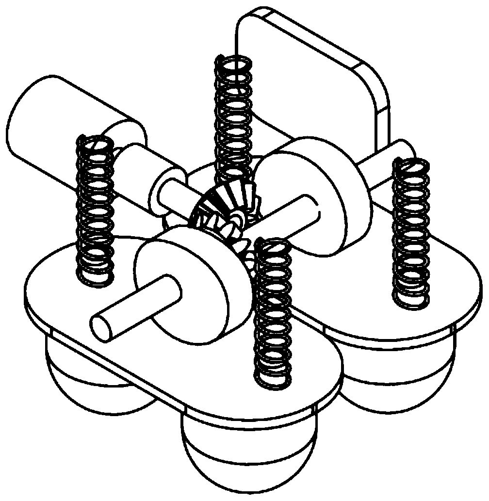
[0029] The motor 12 drives the driving gear 9 through the shaft coupling 11 and the gear shaft 10, and the driving gear 9 drives the driven gear 8 to rotate in the vertical plane. The driven gear 8 is sleeved on the camshaft 4, and the driven gear 8 drives the camshaft 4 rotates, the cam 5 is sleeved on the camshaft 4, and rotates together with the camshaft 4;

[0030] One end of the return spring 2 is connected with the shell 1, the other end is connected with the massage head base 6, the cam 5 contacts with the massage head base 6, the cam 5 rotates, drives the massage head base 6 to move, the massage head 7 is c...


PUM


Abstract

The invention provides a convenient bionic massage instrument structure, which comprises an outer shell, return springs, a camshaft, cams, massage head base seats, massage heads, a driven gear, a driving gear, a gear shaft, a coupling and a motor which are arranged inside the outer shell, wherein the motor drives the driving gear through the coupling and the gear shaft, the driving gear drives thedriven gear to rotate in a vertical plane, the driven gear sleeves the camshaft, the driven gear drives the camshaft to rotate, and the cams sleeve the camshaft to rotate together with the camshaft;and one end of the return springs are connected with the outer shell, the other end of the return springs are connected with the massage head base seats, the cams contact with the massage head base seats, the cams rotate to drive the massage head base seats to move, the massage heads are connected with the massage head base seats, the massage heads move along with the massage head base seats, andthe return springs enable the massage head base seats to smoothly reset after reaching a lowest point. By using a brand-new transmission mode, the noise and vibration are obviously improved, and the active use experience of users is improved.

Description

technical field [0001] The invention relates to a massage health care product, in particular to an internal transmission mechanism of the massage health care product. Background technique [0002] Massage is gradually summed up and developed by the working people in our country during the long-term struggle against diseases. With the rapid development of society and the transformation of medical models, people's pursuit of natural therapy has increased significantly, and the massage equipment industry has developed rapidly. Since the 1980s, after decades of development, massage equipment in China has developed into a huge industrial chain integrating design, production, sales and service, and my country has reached the international leading level in massage equipment. [0003] Among the many massage devices, portable massage devices occupy a large proportion of the market. Portable massagers come in different sizes, ranging from small to medium-sized; the power sources of t...

Claims


Application Information

Patent Timeline
IPC IPC(8): A61H23/02
CPCA61H23/02A61H2201/0157
Inventor 刘晓康陈锦宋江波赵晓文庄天峰朱健恺
Owner 深圳市康瑞普斯医疗器械有限公司
Learn More